| Accessed | times since October 19, 2001. |
| Accessed | times since October 19, 2001. |
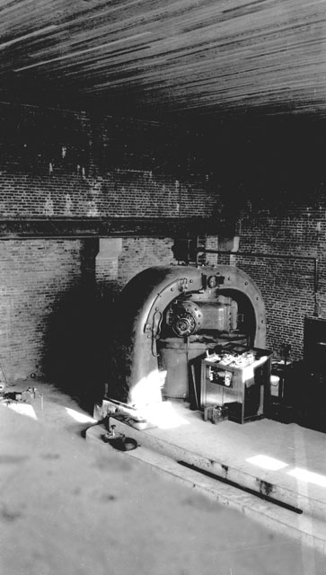
| On August 6, 1918, "High Powered Radio (T) Station, Annapolis," was commissioned using the two 350
kW Poulsen arc converter VLF transmitters seen on this page. By October of 1918, the station was on-the-air using
VLF transmissions. On October 24, 1931, one of the Poulsen transmitters was replaced with a TBC type V.L.F. transmitter. On August 13, 1937 a Helix House building for the new TBJ transmitter was started. On March 19, 1938, the original Arc Converter and Poulsen Transmitters were replaced by RCA TBJ transmitters. |
|
William Du Bois Duddell discovered that a current arc between two electrodes, shunted by a circuit containing a capacitance and inductance would establish an oscillating circuit. The value of the capacitance and inductance determines the frequency of oscillation. The Poulsen system is based on this phenomenon. An arc follows a characteristic, which is the inverse of Ohm's law in that when the current of the arc is increased, the voltage across the electrodes decreases. This characteristic is often called negative resistance. Placing a series LC circuit across the terminals of an arc will initially cause the capacitor to charge, diverting some of the current away from the arc. Given the aforementioned arc characteristics, the potential difference between the arc electrodes will increase, putting the capacitor at an even higher voltage. Once the capacitor reaches full charge the arc current will reverse to discharge the capacitor back into the arc. As the current into the arc increases, the potential difference will fall and the voltage across the capacitor will also fall to a point, which it will begin to charge again. If the circuit resistance is small enough, this process will continue as an oscillation. Duddell found that it was necessary to use a minimum of 1 microfarad of capacitance to obtain oscillations of considerable energy. With this large capacitance, it was not possible to reach high enough frequencies for transmission of Radio-telegraphy. With each cycle, the arc is extinguished for a portion of the cycle. Residual ions in the atmosphere around the arc caused this period of extinguished arc to be erratic to the time of re-ignition. This resulted in a phase "jitter," which impaired its ability to operate at high frequencies. Poulsen realized that in order to eliminate this "jitter," the ions needed to be swept away. A strong concentrated magnetic field would accomplish this. The addition of hydrogen molecules, which were the most mobile, made this "sweeping away" more effective, hence, maintaining a steady phase in the signal. With the added hydrogen atmosphere and transverse magnetic field, it became possible to use a smaller capacitor, resulting in oscillation at frequencies high enough to be useful for Radio-Telegraphy, maintaining high power at the same time. There is a similarity between "making and breaking" arc across a tuned circuit and a more modern class C tube amplifier. Both supply a pulse of energy to a tuned circuit in time with the natural period of the tuned circuit. Also, a tube contains a "gap" between the anode and the cathode. The similarity ends there as the tube gap is in a vacuum and does not act as a negative resistance. The tube pulses are "gated" by a grid structure between the anode and cathode, which is supplied with the RF signal rather than "participating" in the oscillation process. In the actual construction of the Poulsen arc generator, the anode is a copper beak. The cathode is of carbon about 1 inch in diameter with the arc striking between the copper beak and the edge of the carbon. The carbon cathode is fitted in a holder, which is slowly rotated by a small motor. As it burns away the carbon, a fresh surface is presented and the length of the arc is kept constant. The arc length is adjustable by means of a screw fitted to the copper electrode. The electrodes are fed through insulating sleeves in the sides of a water-cooled metallic chamber, which is flanged on the outside to assist the cooling. The poles of a powerful electro-magnet pass through the sides of the chamber, and transversely to the electrodes. The field of the electromagnet pushes the arc out into a loop. The windings of the electromagnets are placed in series with the power supply to the arc, acting as chokes, which prevent the oscillations from passing back to the power supply. The arc chamber is supplied with hydrogen through a tube into its base and after passing through the chamber escapes through an outlet at the top and is conveyed away by means of a tube connected to it. The arc is connected across a 500 volt DC supply and across it is shunted the primary series LC circuit. The antenna is connected to one tap of the inductance and the earth wire to another. Telegraph signaling is achieved by shorting one or two turns of the inductance through a Morse key, which shifts the wave-length of the transmitter by a difference of about 5 percent.
References:
|
| These photos were scanned from negatives (c. 1918) obtained by purchase through an auction. The source of the photographs are unknown. The descriptions on the photos are quoted from the writing on the negatives. Any further information from a credible source would be appreciated. Send e-mail. |
|
|
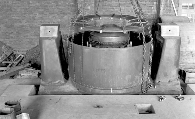
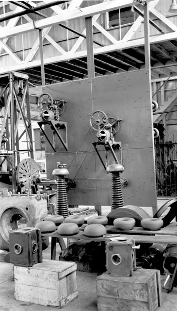
#1 Arc with studs and |
|
|
First Section of Yoke |
|
|
#1 Arc Second Section |
 |
|
|
|
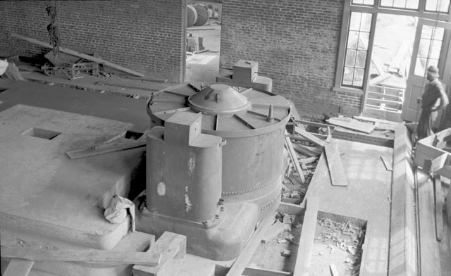
#1 Poulsen Arc Converter |
||
|
|
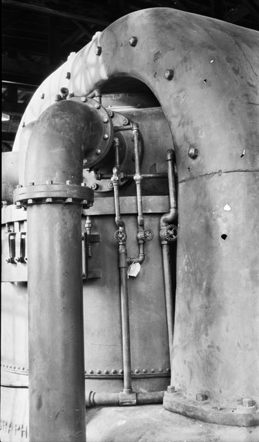
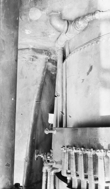
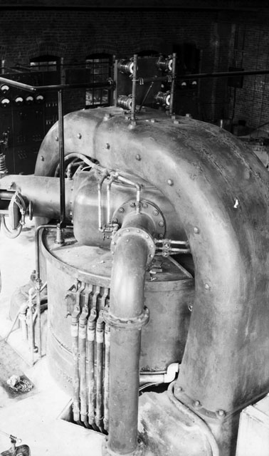
| Original Water Pipes |
|
|
|
|
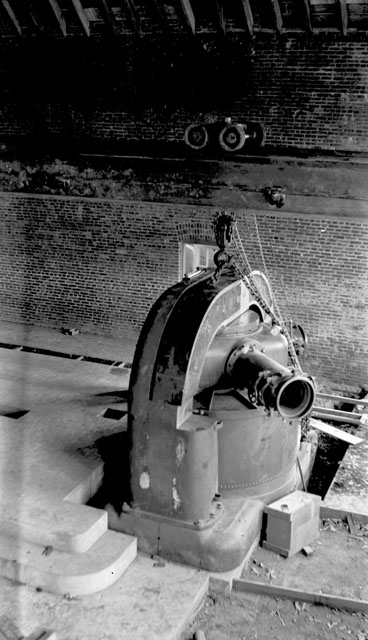
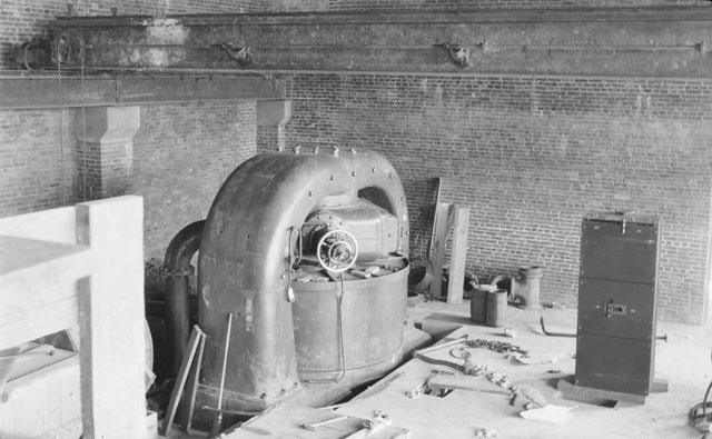
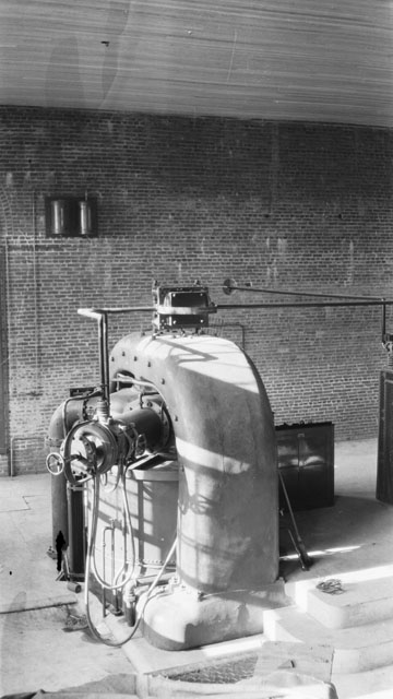
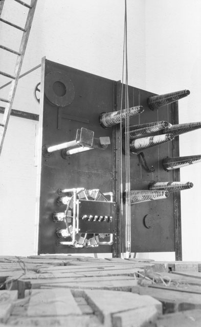
#2 Arc |
#2 Arc |
 |
|
|
|
#2 Poulsen Arc Converter |
||
|
|
|
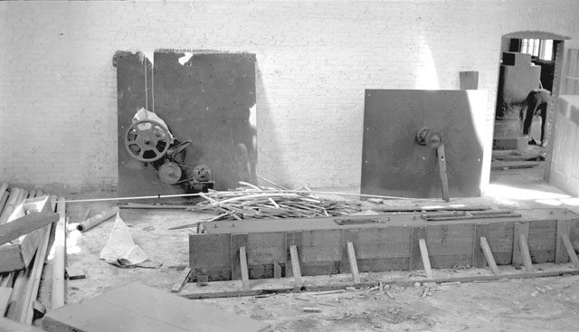
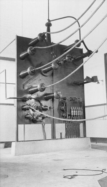
Wave Changer Foundation |
| "The "wave changer" in arc stations was simply a burly inductor, in series with the antenna and loading coil, with a tap switch to change the number of turns being used. This allowed a (limited) choice of operating wavelengths. In one of the photos is visible a circular array of half a dozen posts, these corresponding to the fixed contacts of the tap switch." -- Ludwell Sibley |
|
|
|
|
|
Wave Changer |
Wave changer Erected |
Wave Changer |
![]()
NSS MAIN PAGE |
Links |
| A good modern analysis of arc-transmitter operation by Wm. Byron, W7DHD can be found in Vol. 7 of the Antique Wireless Association "Review." |