![]()
TELEVISION
|
|
|
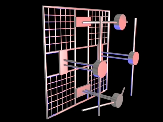
This is the "Turnstile" or "Batwing" antenna configuration, which is probably the most common type used for VHF transmitting, suitable for horizontal polarization only. The rotating animation is just for illustrative effect. The four batwings that make up the turnstile are, in effect, two dipoles which are fed in quadrature phase. This type has excellent omnidirectional characteristics with a minimum of wind load. They are normally arranged in a multiple stack. Click HERE for large, still rendering. |
|---|
|
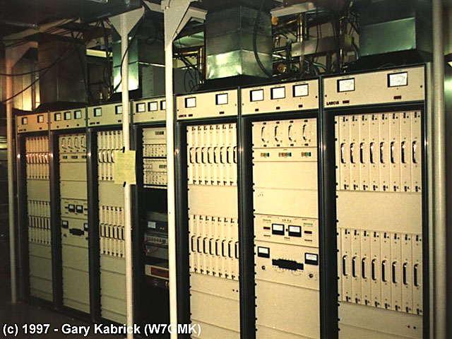
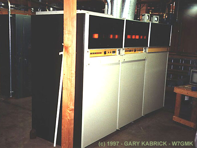
KMSB-TV modern all solid state VHF TV transmitter in Tucson, AZ. It was the first of it's kind in the field. It is capable of running 44 kW, but actually runs about 28 kW |
|---|
Manufactured by Larcan-TTC, the transmitter is made up of four separate amplifier cabinets each capable of 11 kW.
Each amplifier cabinet contains it's own 50 volt D.C. power supply. In operation, each power supply delivers
around 360 amps D.C. depending upon the depth of modulation. The center rack contains exciters, stereo generator,
and audio processing equipment. There are two exciters (one is a backup) which are PIN diode switched.
Transmitter power output control is achieved in the exciters using PIN diode attenuators. Amplifier modules use
four of the Motorola MRF-151G FET. Matching and combining is done using stripline circuit boards mounted
on heat sinks. Amplifier modules may be removed at any time for maintenance without shutting down the transmitter.
Gary Kabrick
|
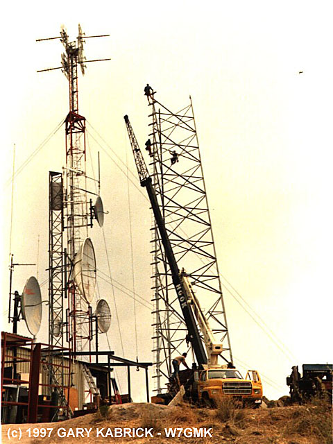
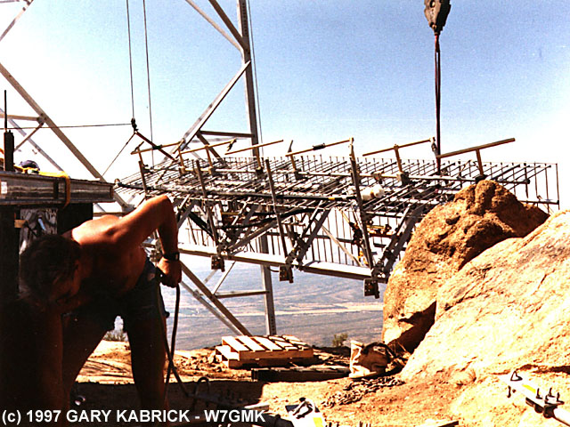
KMSB tower erection. |
The actual antenna, pictured here lying on it's side, has yet to be mounted on the tower. |
|---|
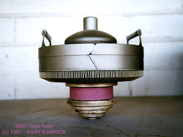
| RCA 30 KW, low band VHF TV transmitter, which uses only 2 tubes, a RCA 9007 tetrode in the visual final and a RCA 8988 tetrode in the aural final. | |
| Photo of forced air coold RCA 9007 tetrode which can operate at up to 400MHZ with a maximum power output of 33KW. For more data, check the Burle website page. | |
| Same RCA 30 KW showing door to the power supply and control cabinet open. | |
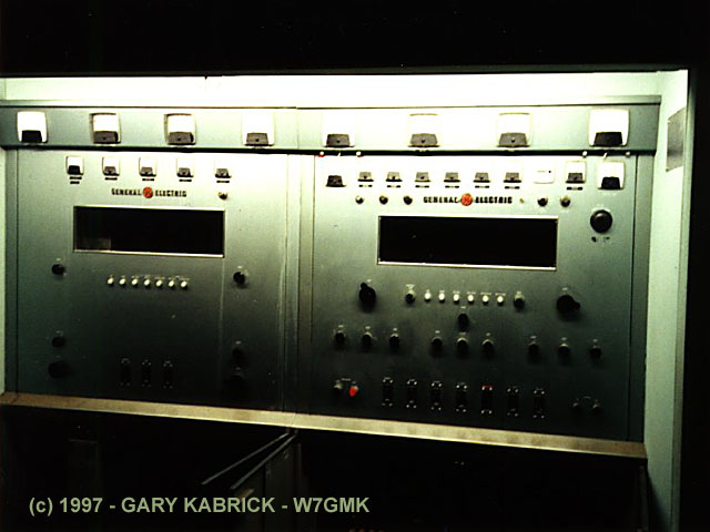
| This is a 5 kw GE transmitter used as the backup at KNAZ-TV. It is all tubes, even the exciter. The left hand cabinet it the power amplifier and the right hand cabinet is the exciter/driver. It is 1970 vintage. |
|
|
|---|
Polarization is the orientation of the electric field with respect to ground as radiated from the transmitting
antenna. When it is parallel to the ground, it is said to be horizontally polarized. When it is perpendicular to
the ground, it is said to be vertically polarized. The polarization can be changed by simply twisting a dipole
antenna to different orientations. Circularly polarized antennas put a "spin" on the electric field as
it propagates. It could be done by spinning a simple dipole antenna mechanicaly at the carrier frequency, but instead
is accomplished by "spinning" the phase relationships between the antenna elements in a specially designed
array like the one shown above.
Circular polarization improves general reception quality in many ways for many different receiving antennas.
Jim Hawkins
Details on antenna polarization can be found in Chapter 8 of the "Television Engineering Handbook"
by K. Blair Benson, McGraw Hill Publishing.
|
|
|
|
|
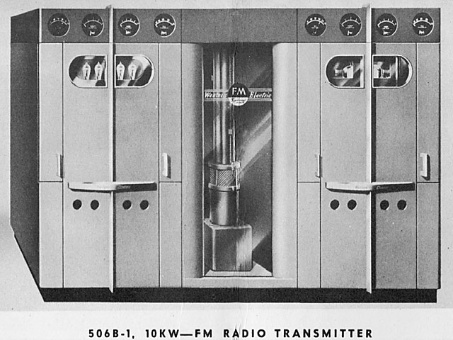
Western Electric Model 506B-1 FM Transmitter picture and logo, Circa 1940s. Image is from
Western Electric brochure. Frequency modulation was accomplished by reactance modulator. This model used a push-pull
reactance modulation to cancel out any power supply hum or microphonics. The cabinets are styled by Henry Dreyfuss.
|
||
 W2XMN Building
  Armstrong Tower
Edwin H. Armstrong's experimental station and tower built in 1938 at a cost of $300,000.00 in Alpine, NJ. Edwin
Armstrong was the inventor of FM radio. The tower rises 410' above the ground can be seen for miles along the Hudson
River and throughout many parts of northern New Jersey, especially Bergen County.
| Accessed | times since March 21, 1997. |
