 |
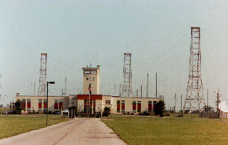
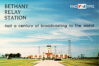
Voice Of America at Bethany, Ohio - Closed in September 1995
|
Please be sure to visit the |
|
to find out about the fine work that is being done to preserve this site |
|
|
Please be sure to visit the |
|
to find out about the fine work that is being done to preserve this site |
Latest Video fromVOA Museum of Broadcaasting |
|
|
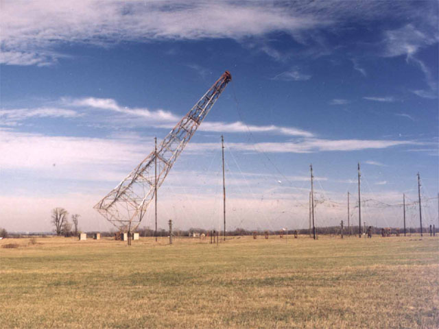
| Voa tower falling in 1996. Photo supplied by Jim Fearing |
| The Bethany, Ohio, Voice of America site featured here was taken out of service in 1995 due to budget cuts. Larger versions of all photos may be downloaded by clicking on them. Jim Hawkins - WA2WHV. |
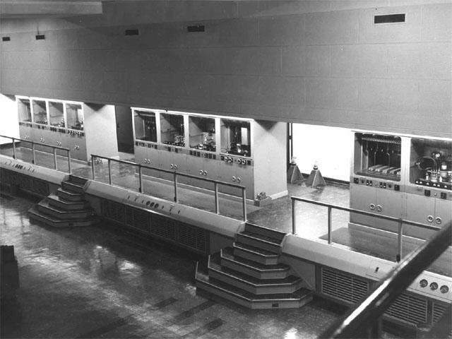
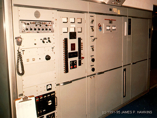
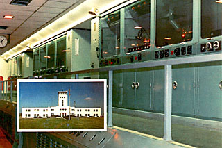
Transmitter and Central Control Console
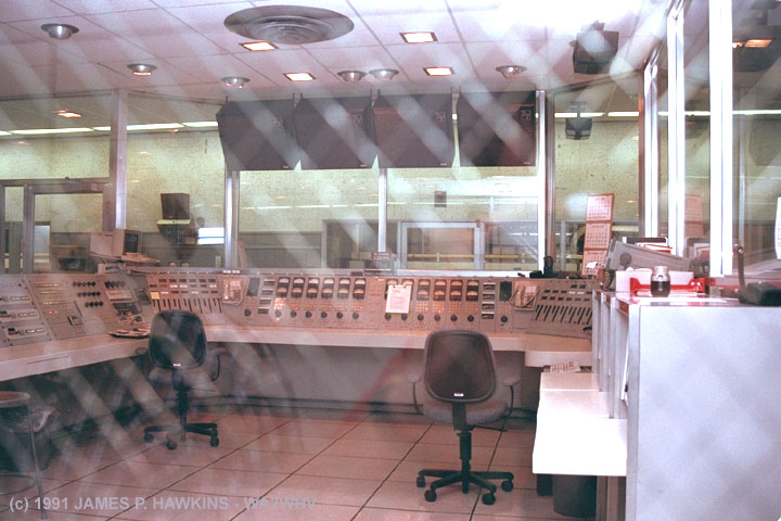 |
| Control Console: Access was restricted. Photo was taken through screen glass. |
|
|
|
|
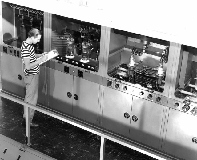
| View of one of the Collins Transmitters | View showing aisle of all three Collins transmitters, fully operational in this photo. | A schematic of the amplifier stages is part of the panel design showing relationship of controls to different stages of amplification on the Collins transmitters. |
 |
| Collins transmitter panel showing beautifully laid out controls and flow chart. |
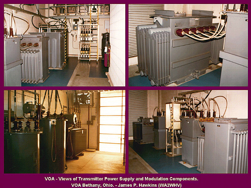 |
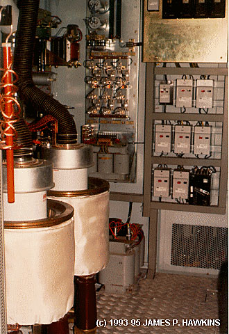
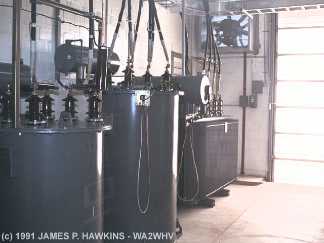
Four views of the chamber containing power transformers, solid state rectifiers, capacitors, chokes and modulation transformers for one of the Collins AM transmitters. The doors to the rooms were interlocked so that all power would be disconnected and capacitors shorted upon entering. The CE told us that an engineer had been "fried" some time ago when he accidently came in contact with a live line. |
|
|
|
|
|
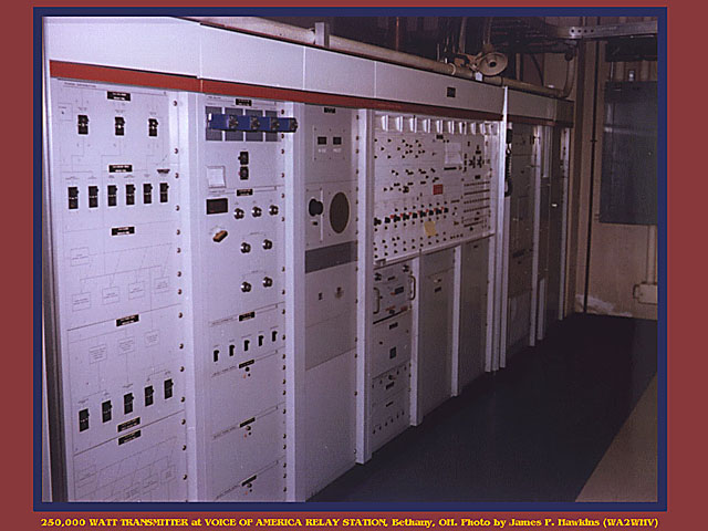
Front panel of 250KW BBC Transmitter |
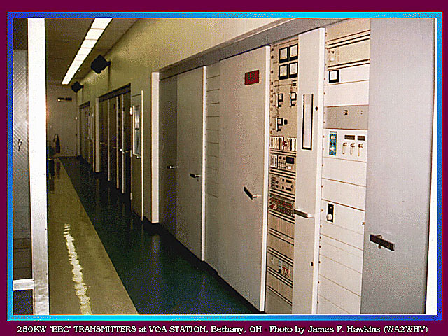
Aisle showing three BBC 250KW Transmitters, where the Crosleys were. |
Open Audio Modulator cabinet with steam cooled tubes (on left). |
|---|
 |
|
Modulation Transformer |
|
The BBC transmitters used vapor cooling for the final transmitter tubes. The tuneup procedure is computer automated. These transmitters were in the process of being installed when I first visited the site in 1993. They were replacements for three Crosley transmitters. Below is an interesting story sent to me by Bruce McLaughlin - W8FU. |
|
When I toured [the Bethany site], they still had three old Crosley 175 KW transmitters along with the three 250 KW Collins units as well as a very old Collins 5 KW SSB unit. The Crosleys were the originals (they had six at one time but three were replaced by the Collins units). The Crosley units were manually tuned. And to get down to the 6 Mhz region, it was necessary to crawl under the units and insert a Jennings fixed vacuum capacitor. The engineer let me crawl in with him when he did this! The power switches were actually padlocked when they did this. Except for replacing the original mercury vapor tubes with solid state rectifier stacks, the transmitters were more or less in the original state. They had a lot of glass doors so you could see most of the innards. The Crosleys were replaced by the BBC units in your shot. At the same time they spent a lot of money remodeling the place, including asbestos removal and getting rid of the old huge PCB laden transformers and chokes. Within a few months of completion, the place was closed! The transmitters were shipped to Sri Lanka. The antennas are still there. Bruce -Bruce D. McLaughlin - W8FU |
|
|
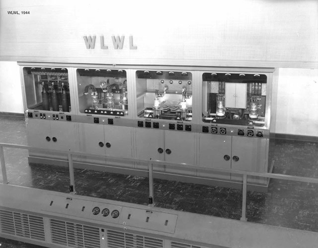
View of Crosley Transmitters in 1968. Formerly these transmitters were WLWS, WLWR and WLWL. From the files of Westchester Township, OH Supplied by Jim Fearing |
|
|
|
| Two views of one of the three Crosley transmitters, which were in service from 1942 to 1989. They were replaced buy the ABB Transmitters shown on this page. Photos (taken in 1944) from the files of Westchester Township, OH Supplied by Jim Fearing |
|
The Late Clyde G. Haehnle (1922-2018), who worked for WLW, on the CrosleysWhen we were in the commercial international broadcasting business we had one 50KW Crosley
designed and built short wave transnitter. It's call was WLWO. During the early part of the WW II the OWI
(Office of War Information) sent us an RCA short wave RF section and we acquired a modulator and power supply from
KFAB in Lincoln Nebraska. This composite went on the air from the Mason, OH site as WLWK. Later when we got the
Bethany VOA plant on the air we used the Call letters of WLWL, WLWR and WLWS for all six transmitters. Bear in
mind that we had six RF carriers and only three power supplies and modulators, therefore, each program was carried
on two frequencies. In the very early days pre-war we had a 1 KW short wave transmitter operating in the 6 Mhz
band with call letters of W8XAL. For many years this transmitter operated continuously for the National Bureau
of Standards for recordings of solar flare activity. At one time we held every call from WLW to WLWZ. |
|
|
| This transmitter is used as an emergency relay to another site, in case other links fail. |
 |
|
Tube Storage |
 |
The antenna switch is a matrix of completely hand operated switches. There is no remote control. Engineers must leave the building, enter the matrix and set up the individual switches to change antenna configurations. I asked why it wasn't more automated. The engineer giving us the tour said quite simple, "because it works fine the way it is". |
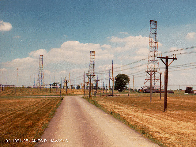 |
View of antenna farm showing two curtain antenna arrays and rhombics scattered about in the background. |
For an antenna farm layout, description of antenna direction and coverage and a brief history of the site and why it was placed in OHIO, click on the link.MAP OF BETHANY ANTENNA FARM LAYOUT |
 |
 |
| This QSL shows the three Crosley transmitters, which were in service from 1942 to 1989. They were replaced buy
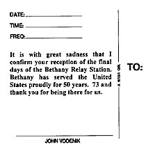
the ABB Transmitters shown on this page. (Kindly supplied by John Vodenik - K9HSP) |
 |
 |
|
Having been employed at Bethany Relay Station for almost 10 years, I have a few stories I would like to tell. Spark TransmitterI'll start with the spark transmitter that a few of us constructed one slow Saturday. Since our primary function
as technicians was to: 1. Get the transmitters on and 2. Keep them on, when things are going well, we kind of get
bored. Back about 1994, a couple of us decided to see what it was really like back in the spark days. We gathered
up a few transmitting caps from the Crosley transmitter stock, wound a couple coils, and built a spark transmitter.
It was "breadboarded" on the workbench in the electronics repair shop. The antenna ran from the top of
the guard tower, about 80 feet high, down to the front of my truck. From there, the wire ran into the building
through a piece of fiberglass tubing, and connected to one of the caps. To get the high voltage, one of the guys
brought in a furnace ignition transformer, so we had about 10,000 volts AC We found a CW hand key in my locker,
and connected the 110 VAC from the wall outlet through the key contacts, and on to the transformer input.
Fire in the Hole
OK, have you ever really seen the color "electric blue"? I have, and it is something not to be
forgotten. Late one afternoon, it came time to kick the tires and light the fires on one of the Collins 821-A1
250 kW transmitters.
Hurry up and Wait
|
| Accessed | times since April 1, 2001 |
© 2003 James P. Hawkins - WA2WHV