|
|
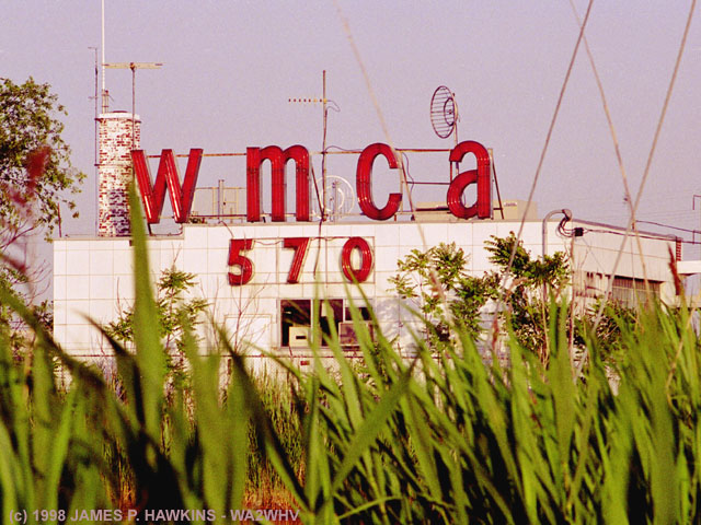
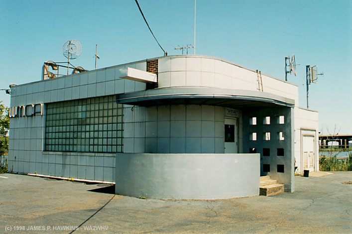
can be seen from the NJ Turnpike just north of
the Pulaski Skyway near Newark
|
|
All Pictures with borders can be clicked on for an enlarged version.
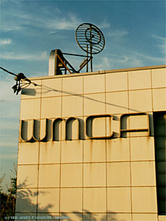
| In the 60s, WMCA was the home of the top 40s WMCA "Good Guys." Some of those Good Guys, such as Harry Harrison and Joe O'Brien can now be heard on WCBS FM 101.1. See links at the bottom of this page for more. |
ACKNOWLEDGMENTSI would like to thank Tony Dee (DeNicola) - WA2IHZ, and his son, Brian, for the tour of this site. Tony has been working at WMCA since 1992. Tony co-owns WODI AM 1230 with Dave Marthouse - N2AAM in Brookneal, VA, a small, beloved Mayberry-like town only about 120 miles from Mt. Airy, NC where Andy Griffith was born. Tony spent many hours with me at the WMCA site going over the equipment, telling me stories, looking through files for important historical information and most of all, really made me feel welcome. Tony and his son Brian are two great guys, whom I am glad to have met. Brian is looking forward to a career in radio and has, in fact, started that career. I wish you the best of success and fun, Brian! I would also like to thank Pete Tauriello, shadow traffic reporter for WINS, for his encouragement and connecting me to Tony for this tour, taken on 6/9/1998. Pete has also been a real boost for me. |
CONTENTS |
|
|
|
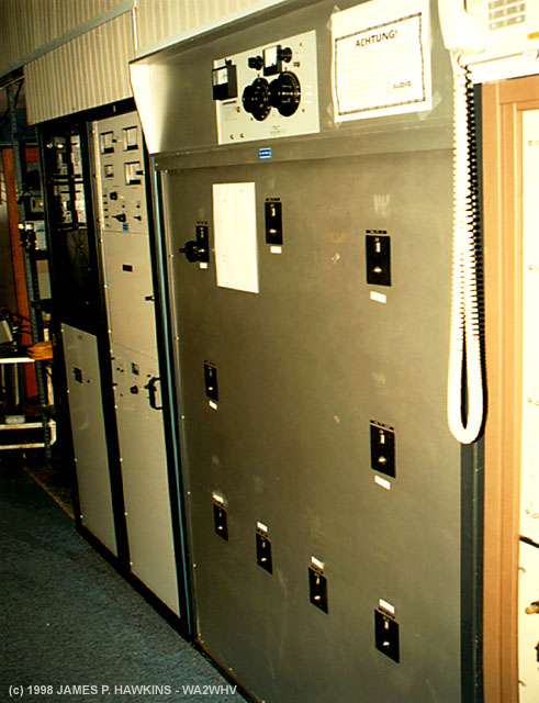
WMCA Transmitter Building |
This Building now houses both WMCA and WNYC AM transmitters. The outputs are diplexed at the antenna towers, allowing the two stations to share the same 3 towers. Part of the diplexing process is to add band stop filters to each transmitter output to prevent the RF signal from each transmitter from feeding back into the other transmitter.
|
|
|
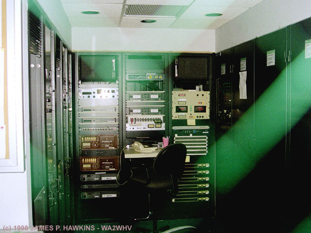
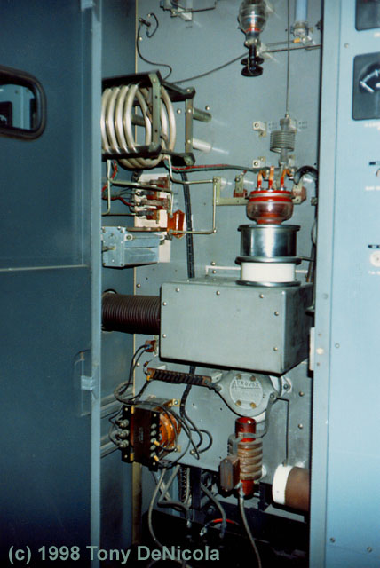
WNYC transmitter and equipment |
|
|
Microwave feed dish pointed toward the WMCA studios in Rutherford, NJ. This dish is also visible in the head picture on this page. |
|
|
Input processors, compressors, and other controls. |
|
|
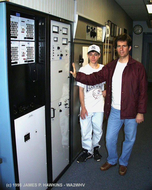
Main Nautel 10KW* Model AMPFET ND-10 (running at 5KW) solid state transmitter with Pulse Width Modulation (PWM) on the collectors. Chief Engineer, Tony Dee, and his son, Brian, at right. |
|
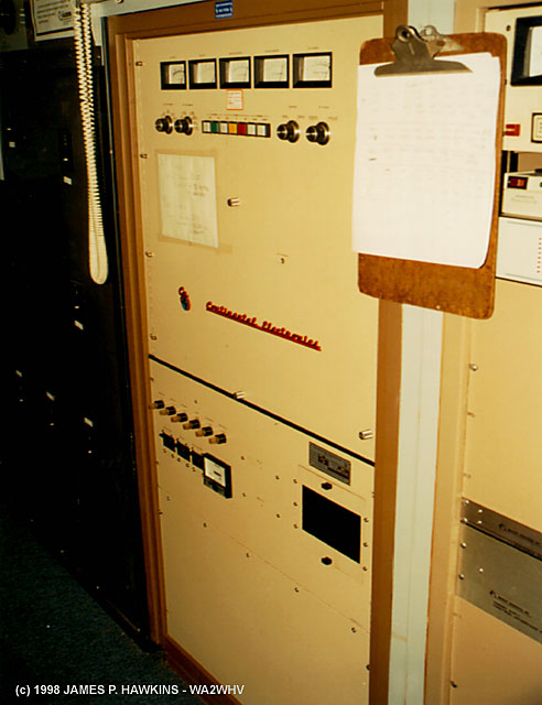
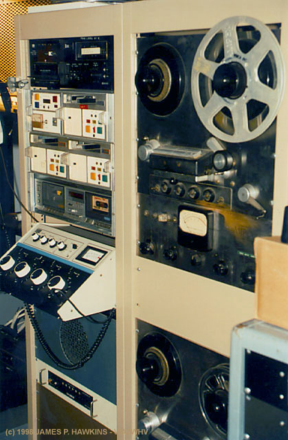
Continental 5KW Model 315R-1 standby transmitter. It uses a "dc coupled series switching modulator." |
|
*The Nautel AMFET ND-10 is a 10KW transmitter. The power supply is capable of 10KW |
|||
|
|
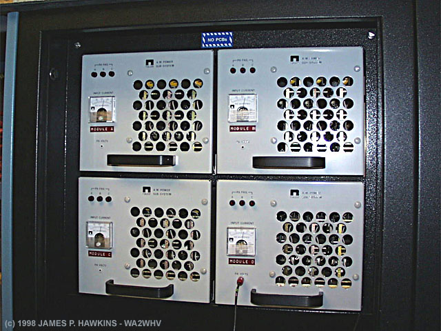
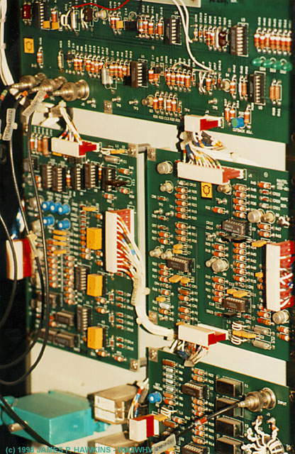
The Nautel is composed of four RF amplifier modules, each rated nominally for 1.4 KW. The modules each contain, PA/Modulator Assemblies and are all modulated equally. The outputs are combined to obtain the full 5+ KW. If a module should fail, it can be removed and replaced with another module while the transmitter is operating, causing only a brief power reduction during the change. Each module is broken down further into 3 boards. |
|
|
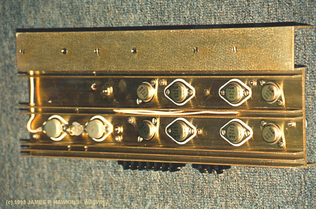
Top of individual transmitter module board. There are three of these boards per module, designated as 'A', 'B'
and 'C'. Three indicator lights on the parent module indicate if a board has failed. |
|
|
Flip side of transmitter module board. These boards "buzz" with the sound of the audio modulation. |
|
|
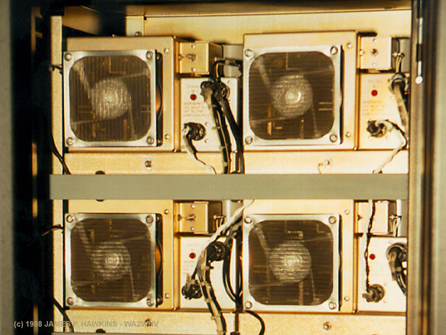
View of rear of the four modules, each with its own cooling fan. It used to be that a 5 KW transmitter required enormous, noisy blowers making the transmitter room sound like a ship's engine room. This one is cooled with four muffin fans, not much louder than a PC cooling fan. Even though there is actually more power, modern transmitters do not give you the old time ambiance of power, including the heat. |
|
|
This is the digital control board. |
| Pulse modulation is called Class 'D' modulation. In a class D modulator, active elements (transistors) are never in a partially on or off state. They are either fully on or fully off. In these states, transistors dissipate a minimum amount of power. Either the current is near zero or the voltage is near zero so that the resulting power dissipation calculated as the voltage times the current (E * I) always results in a very low value. There are different types of class D modulation, but all are accomplished by using transistors as switches. In the case of Pulse Width Modulation, as the audio wave increases in value, the amount of time the transistors are switched "on" (duty cycle) is longer than the time they are switched "off." As the wave falls, the proportion of time "on" to time "off" is reduced and eventually reverses. Another characteristic of class 'D' modulation is a positive peak modulation which can go beyond 100%. How is this possible without clipping of the negative modulation peaks? Unlike the old high level plate modulation methods, with Class D modulation, the carrier can be controlled to "float" to a higher power when the modulation is pushed past 100%. I believe the FCC allows a maximum of 125%. |
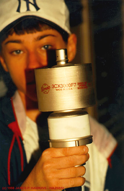
The Continental 315-R1The Continental Electronic transmitter uses air cooled 3CX3000F7 tubes in the PA in the modulator. The 315R-1 is a PWM transmitter. According to David Herschberger of Continental Electronics, the 'R' in the transmitter model number referred to "Rockwell" from Collins/Rockwell which came out with what was called "The Power Rock" design. Otherwise most other tube designed Continental transmitters used Doherty linear modulation. Description of the 315R modulation as explained by "High level amplitude modulation is normally achieved by varying the plate (and screen) voltages of
an RF amplifier tube. This varies the RF output of the tube, producing amplitude modulation. The voltage applied
to the tube consists of a DC voltage plus audio. There are many ways to produce this combination of DC+audio. Early
AM transmitters did it in a straightforward way: a high level audio amplifier produced the audio, which was then
added to DC with a coupling capacitor and a modulation choke. |
|
My own analysis (stick my neck out department) This design reminds me of the method used in DC switching regulators, for which I was on the development team at Singer General Precision back in 1967-1969. The input of the regulator was a full wave rectified power source. As the voltage varied, a switching or "pass" transistor would gate the current at a varied pulse width accordingly and the pulsed output would be passed to a filter network to smooth out the output. The output would be compared to a zener diode as a reference and the difference between the reference and the sampled output would determine whether the output would be switched on or off. The higher the sensed voltage, the narrower the pulses. The lower the voltage, the wider the pulses. The output was, of course a steady DC value, as long as the average input voltage source was higher than the output. Now consider what would happen if the zener diode was replaced with an audio signal and compared to another reference, removing the comparison (feedback) to the output. The output of the power supply would become a power audio source, since the new reference voltage is no longer a DC voltage, but a voltage which varies with an audio signal. This is all accomplished by switching transistors completely on (very low power dissipation) and completely off (no power dissipation). The only devices which would be operating in an active Class 'A' manor would be the very low level voltage amplifiers for the input. This is a simplified, but this seems to be the principle involved in the modulation technique explained by David Herschberger. In the 315R, the single 3CX3000F7 modulator tube, takes the place of the pass transistor. It acts as the final high power switch before filtering. On the other hand, Doherty Modulation is a modified linear amplifier, low level modulated at the driver stages. What distinguishes it from others is that it uses two RF output tubes, one which handles the carrier and the negative modulation swings (the "Carrier tube") and the other tube (the "Peak Tube"), which normally is cut off, but goes into action during the positive peaks of modulation. The 315R shown here, however, was an exception. |
|
|
This picture shows Brian holding one of the 3CX3000F7 tubes. |
|
|
|
OK, I'll be honest, this is a pose, but Tony |
|
|
Antenna phasing unit allows each tower to be fed at a different phase, relative to other towers. This phase relation, causes different degrees of radiation cancellation to create a desired pattern of directional coverage. Stations with one tower, are omnidirectional. |
|
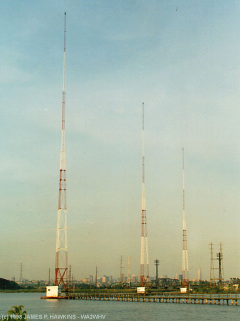
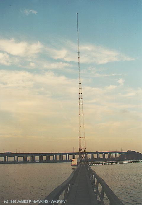
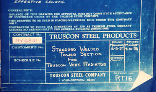
Three-tower array phased to cover mostly New York City. Antennas were built by Truscan Steel Products. The Empire State Building can be seen in the distance at the right of the farthest tower. WNYC has a slightly different directional pattern. |
 |
|
Part of tower blueprint shows dates of 12/8/1937 |
BIRDEX!
If you're standing on the WMCA tower catwalk
you will hear THIS!![]() or, maybe THIS!
or, maybe THIS!![]()
The sound is far more impressive when you're there. It is intended to
discourage birds away from the towers. It triggers periodically with
a few different sounds and adds to the somewhat mystical feeling this place.
|
|
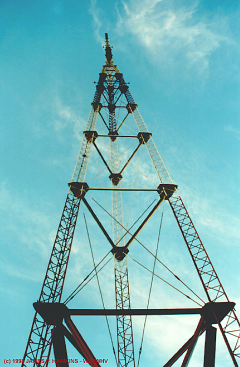
From afar, these towers look fairly ordinary, but up close, the structure is exceptionally beautiful with great detail. (Click on photo) |
|
|
View of tower foot showing porcelain insulator, Austin Isolation transformer for tower lights, tuning house to left and NJ Turnpike in the distance. The dark mass on the tuning house is a mass of flying insects called midgies. There are swarms of these insects in the meadows. Fortunately they don't bite. I had to spit one out of my mouth. I wasn't sure of its nutritional value. |
|
|
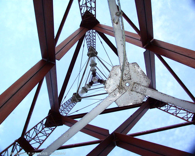
Looking straight up into the tower. Notice the RF feed directly to to a center, hexagonal plate. This distributes the current equally to the three sides. |
|
|
View down catwalk to first tower with NJ Turnpike and Laurel Hill (nicknamed "Snake Hill" mountain) at the right. If you commute from Newark, NJ to Penn Station, NYC on a train, you pass the foot of this mountain. |
|
|
|
Brian is showing the size of this |
|
|
|
|
|
Spare studio which can |
Emergency Diesel Powered |
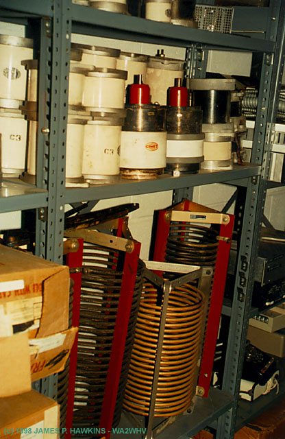
One of the spare parts |
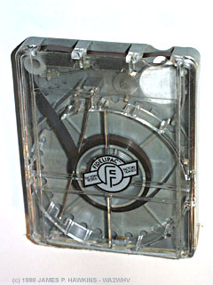
A "Cart"
|
|
|
Broadcast continuous loop |
|
|
|
|
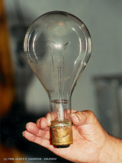
I used to think tower lights were just |
This is the type of light bulb that is used |
|
|
|
Looking back at the transmitter |
|
|
|
|
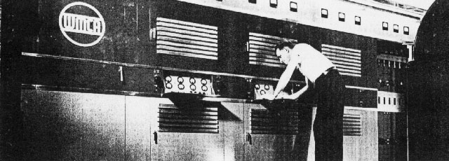
Prior to the Nautel was the RCA |
Open PA cabinet of the BTA-5U1 |
|
|
|
Master Control Room in New York City |
|
(From WMCA Brochure supplied by Tony Dee) |
|
This 5KW RCA transmitter installation was completed in 1940. Recollections of Pete Tauriello of WINS News Jim- |
|
On January 21, 1999 at about 01:20AM Tony Dee had to shut down the WMCA transmitter for maintenance. Here are the sounds heard on 570 KHZ just before and about 1.5 minutes after WMCA dropped out. First the shutdown announcement, then the carrier drops out revealing a Spanish speaking station and a ticking noise every second and a beep every minute on the minute followed by two morse code Rs. I posed a question as to what I was hearing on New York Radio Message Board and was told the following:
- Tom Sanders The Spanish-language station with the time pips and Morse "RR" identifier on 570 is CMHI, Radio Reloj, in Santa Clara, Cuba. Radio Reloj is Cuba's national time-standard station and is based in Havana. It has transmitters all over the island...its Havana outlet is on 760 (CMCD). The format of Radio Reloj consists of two announcers taking turns reading news with time pips superimposed. Time checks are given on the minute, followed by a brief time tone and the "RR" sounder. There are no commercials. - Phil Galasso Cuba is about 1500 miles away and from here and groundwaves from Cuba are almost completely over ocean salt water, unobstructed by any land. |
|
|
Click this button. |
Fine Print:
All images are Copyrighted and are provided for your personal enjoyment. Use of these images for commercial purposes
including their distribution on CD-ROM or any other media without my permission is prohibited. Contact: Jim
Hawkins