JIM HAWKINS' WABC RADIO 77

Transmitter Page

Front panels of GE Model BT-50-A 50KW Transmitter with High Level Plate Modulation
View location map.


After touring this page, see the WABC Transmitter site as it appears TODAY with new, digital AM transmitters!

This is a private, non-profit page created by Jim Hawkins not affiliated with WABC.


These photos were taken at the WABC transmitter site in Lodi, NJ on August 12, 1966 when WABC was called 
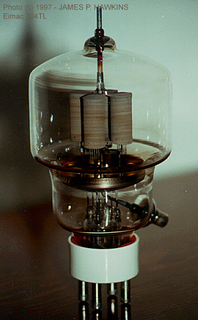
"Music Radio WABC". The late, Wayne Ely - W8LBB, was the transmitter engineer at the time.


Wayne Ely had passed away at 63 recently at his Ohio home while chopping wood. He was a fun guy and a great engineer. He lived in Fort Lee, NJ when these pictures were taken. I hadn't seen Wayne for many years, but in his memory, I am thankful to him for his hospitality, friendship and his fun filled, youthful nature. I had visited him at his home a few times in the 60s where he made my friends and me feel welcome. I also thank him for the opportunity to take the photographs which made this page possible! He will be missed by his friends and family.
Other contributions are annotated where appropriate and all contributors to the radio page are listed in the contributors list on the main page.

The background was created from a photograph of an Eimac 304-TL tube, the type of which was used in one of the amplification stages of the WABC transmitter. I remember peering into the small window port of the 50KW transmitter, seeing them glow red hot! The tube I photographed was purchased recently at a ham fest, then I did some Adobe Photoshop magic on the image to give it the "hot" effect. Jim Hawkins - WA2WHV.


WABC 770KHZ, New York, NY
with transmitter located on Route 17, Lodi, NJ. August 12, 1966
The single, omnidirectional tower height was and still is 648 ft.
It all began in the
darnedest of places!


August 1962

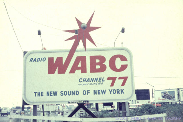
WABC billboard as seen at the entrance
from NJ Rt. 17 south.

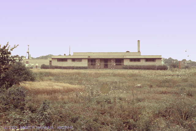
WABC Transmitter building as seen from
NJ Rt. 17 south. As of today, May 23, 2017,
the building is no longer visible from NJ 17.
The grassy area is now completely occupied
by industrial buildings right up to and within
a few hundred feet ot the WABC building.

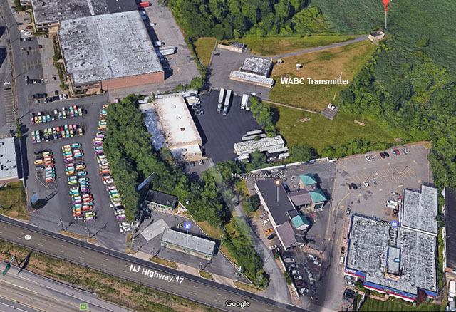
As of today, 5/23/17, the WABC transmitter building is obstructed by numerous structures, making
it invisible from the old viewpoint from NJ Route 17.


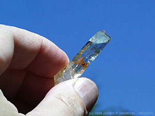
IT ALL BEGINS WITH A
QUARTZ (SiO
2) CRYSTAL!

This is a naturally formed specimen
of Quartz crystal from my own
collection. The specimen is from
Arkansas, USA This mineral, when
sliced properly, is like an electric
pendulum, which keeps the time in
our watches and clocks; generates
the clock cycles in our computers,
which step through instructions in
the microprocessor; and generates
the radio frequency waves that carry
radio messages, to mention a few.
Quartz is also used for its intrinsic
beauty in jewelry.


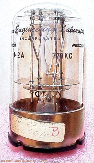
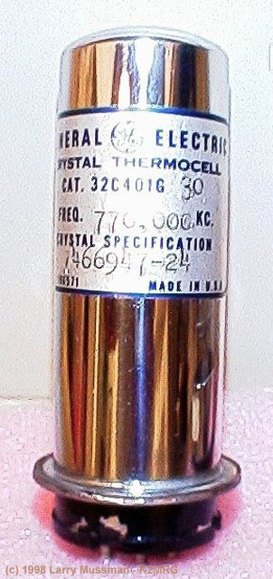
The photographs below are of the crystals used to generate the radio frequency signal for 77 WABC. They are out of the collection of Larry Mussman - K2MRG who was the transmitter chief engineer after Wayne Ely left for Ohio. Larry kindly contributed these pictures. These are
photos of the actual crystal units which made it possible for you to hear the sounds of Musicradio 77!

These are not tubes. They are containers of slices of quartz crystals which have a resonant frequency of 770,000 cycles per second. A crystal is a mineral that grows naturally in cavities of rock and is mined and used for many purposes. Crystals have a characteristic known as the piezoelectric effect. When a steady electrical voltage (force) is applied to electrodes holding the crystal, it contracts. When the polarity of the voltage is reversed, the crystal expands. When this configuration is placed in an amplifier in the appropriate manner, the crystal will expand and contract at a steady frequency and cause the voltage applied to it to vary at the same rate. This circuit is called an oscillator, which is the source of the radio frequency signal. It is then amplified numerous times by the transmitter which feeds the signal to the antenna or tower. So, the sound of Cousin Brucy, Dan Ingram, Herb Oscar Anderson, Charlie Greer, Harry Harrison, the Beetles, Elvis and all the others were carried by a signal generated by this tiny "glasslike" mineral vibrating at 770,000 times per second, putting the station at 77 on your radio dial. In the upper, glass package, you can see the actual crystal suspended at the center of the container. The frequency of these crystals were kept more steady by running them in ovens with very closely controlled temperatures during operation.

The (glass) crystal assembly was used for the Continental 10KW standby transmitter. The lower unit was used for the main GE 50KW transmitter.

Oscillators could run with tuned circuits consisting of a coil (inductance) and capacitor. A crystal takes the place of these components to create a very pure, stable radio frequency signal which does not drift all over the dial and creates a purer sinewave which is free of harmonics. The Federal Communications Commission requires that broadcast stations be run at very accurate, steady frequencies, hence, crystals are used.


TRANSMITTER FRONT PANELS AND CONSOLE

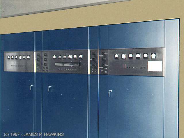
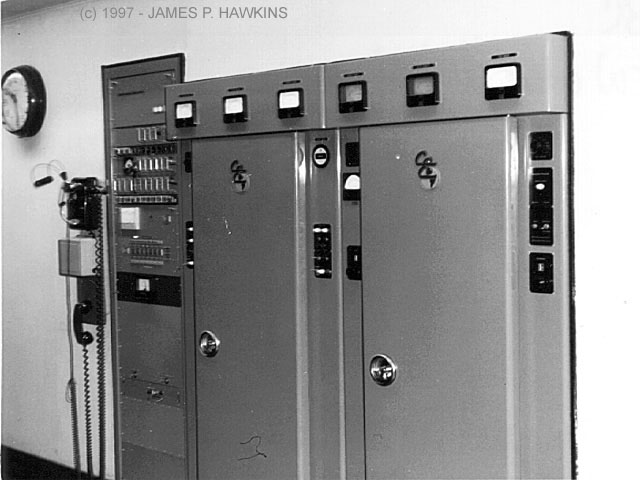
GE 50KW Model BT-50-A HI LEVEL MODULATION TRANSMITTER.
The high voltage supply to both the modulator and final amplifier is 9000 Volts. At 100% modulation, each modulator tube draws about 3.5 amperes. The final amplifier draws about 8 Amperes (4 amperes per tube). That's 72KW input power for 50KW output or 70% efficiency. I've been told that the electric bill is about $5,500.00/month for this model in one station using it today as compared approx. $1,800.00/month to run the new HARRIS DX-50. This would vary somewhat, depending on the location, of course.

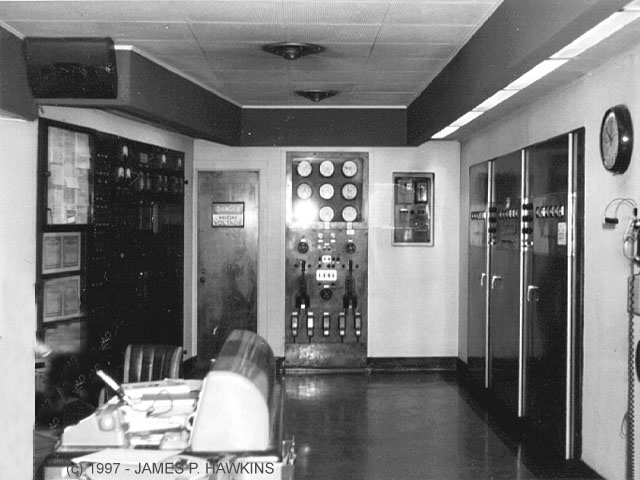
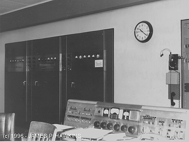
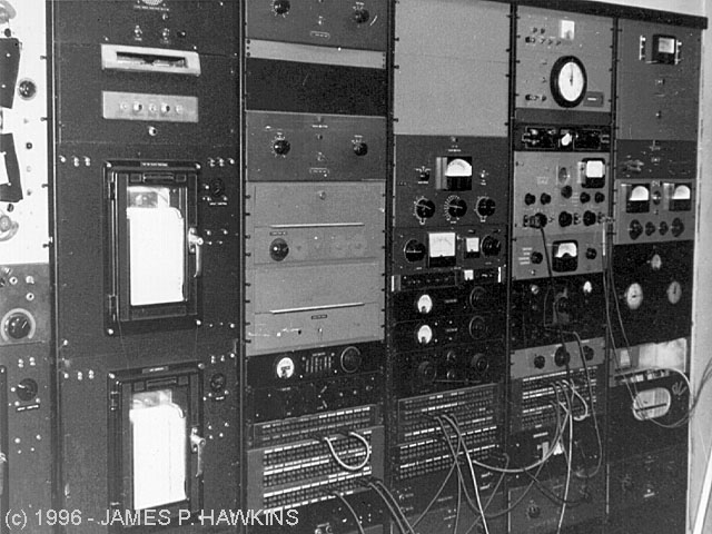
Wide view of transmitter room with 50KW XMTR on Right, Power Control panels on left and far end and console in foreground.

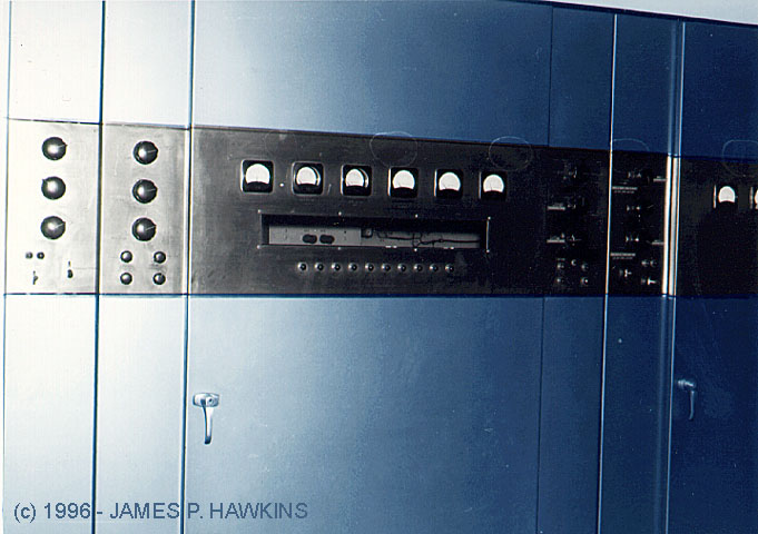
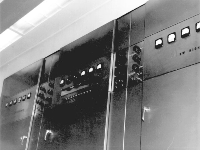
Another view of the GE 50KW transmitter.

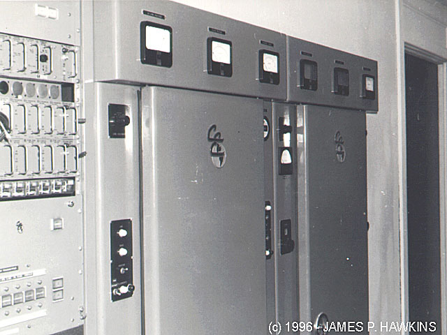
10KW Continental Model 316B Emergency Transmitter

WABC Main 50KW GE Transmitter

View of Transmitter from behind main console.

10KW Continental Emergency Transmitter

Four 304-TL, Low mu, power triode tubes operate in push-pull/parallel in a cathode follower configuration to drive the modulator tubes. They have a beauty of their own with a unique 4-barrel anode which glows red under normal maximum operating conditions.

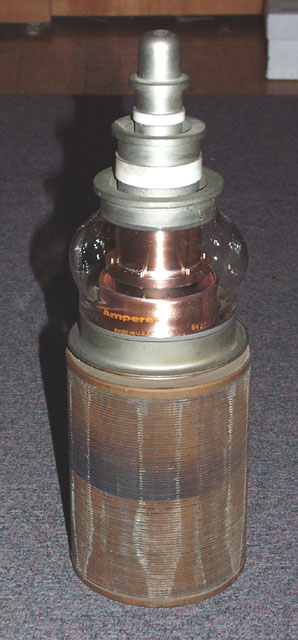
The final output tubes, a pair of 6427s could be seen glowing through a small window in the back of the transmitter. The modulator also used a pair of these tubes. They appeared to be about 12" or more in diameter. This one was given to me by Watt Hairston
CE of WSM. It came out of the same model transmitter.
It is about 16" tall.
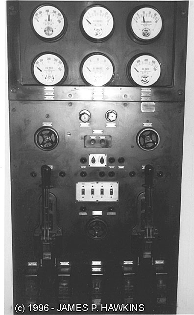
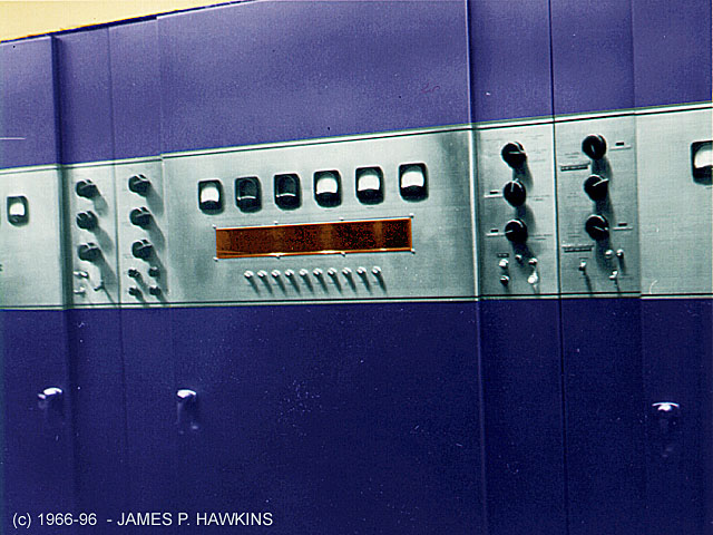

OTHER EQUIPMENT

Main Power Panel

Audio Patch, Chart Recording, Crystal Exciter/oven and other Equipment

"Modulation Cage", located in back of the 50KW Transmitter. Contains modulations chokes and Modulation transformer (abt 3' high) at the far end.


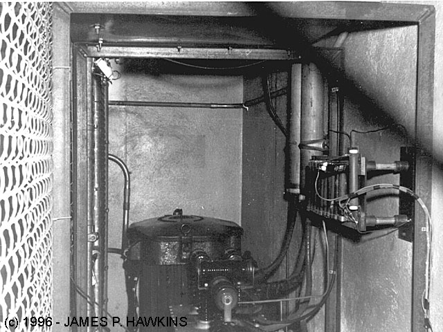
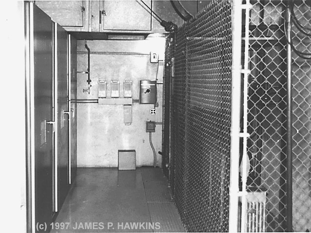
Power panels on wall opposite transmitter.

Room behind transmitter cabinets showing the aisle between the 50KW transmitter and the modulation transformer cage.


THE BIG SOUND! HOW WAS IT DONE?

Remember the unmistakable reverberation on the sound of WABC? Well, at the time of these photos it was mechanically done with a large metal plate suspended by springs! Jonathan Wolfert, President of JAM Creative Productions, identified it as an "EMT 140 plate reverb unit".
(JAM produces radio jingles and if you go to their web page by clicking on JAM above, you can order copies of past and present radio jingles.)

In a front room at the transmitter site behind some of the equipment was a big wooden box the shape of a small bed mattress, containing a mechanical plate reverb unit. The mechanical vibration from the signal was mechanically applied to the metal plate at one point and sensed at another with electrical "pickups" with a resulting added reverberation. The reverberation was mixed only to a certain extent to create just the right amount. The decay time was controlled by a mechanical damper which determined how long the plate was allowed to resonate. An example of a mechanical damper is an automobile shock absorber.

Jonathan pointed out to me that the reverb could be controlled remotely from a panel in WABC's "News Control", which was adjacent to the main studio 8A. During the late 60s they routinely turned off the echo at the end of Dan Ingram's show (5:55pm) and didn't turn it back on until Cousin Brucie began (7:20pm). The time in-between was a network and local news block. He also pointed out that sometimes they'd forget and the news would go out with echo... or Brucie would come on bone dry.

You could find smaller versions of reverb in organs and guitar amplifiers of the time, but in most small reverb units, this is accomplished only with springs because of space limitations. I believe the spring technique was a developed by the Hammond Organ Company, but I may be wrong. Now, this effect is easily achieved with digital effects boxes about in 2 or 3" high rack mount units or simply with your computer sound board. This effect is now used at WCBS-FM to recreate the old sound, but I honestly do not know what they use. I have a Lexicon LXP-15 digital effects unit myself, one effect being called plate reverb.

Jonathan told me that they later reduced the size of the mechanical units by replacing the large, heavy metal vibrating plates with gold foil.

As a side note, I made my own mechanical reverb unit by breaking open two crystal phono cartridges and removing the crystals, each with the pair of wires intact. I bent two ends of the spring so that I could glue the flat crystal units between two windings and suspended it between two hooks. I applied a low level signal to one crystal (yes crystals work in reverse) and wired the leads of the crystal at the other end to the input of an amplifier. Bingo! I had my reverb.


EMT 140 plate reverb unit


WABC EMERGENCY GENERATOR

Dynamotor

Newer Dynamoter for emergency power


READY FOR THE HEAP

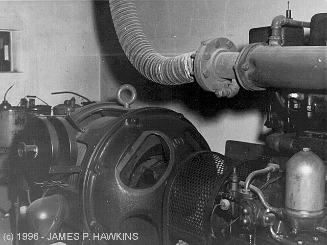
HUGE 6 Cylinder gas engine (just prior to removal)

150KW Generator Driven by the aforementioned 6 "banger"

Old modulation transformer and chokes ready to be "recycled".


EMERGENCY!
WNBC Borrows WABC's Transmitter

This text was corrected. I originally thought it was WCBS that used the WABC facility, but was corrected. Sorry for the misinformation!

WNBC and WCBS used to transmit from the same tower on City Island. Both signals were fed to the same tower. Someone told me this was easy because of the relationship of the two frequencies (WNBC at 660 and WCBS at 880). On Sunday, August 27, 1967, private aircraft smacked into the tower and knocked both stations off the air. WNBC borrowed WABC's smaller tower and emergency 10KW transmitter! I was told that WCBS used a loaner from WLIB which could hardly be heard on the first day of their new All-News format. I remember hearing the audio signal of WABC "leaking" through on the WNBC signal. WNBC explained the "leakage" regularly, so people would understand. It's hard for me to understand why they couldn't prevent the audio leakage, except that the second transmitter and antenna were never intended for that purpose and when you rig up something quickly in an emergency, there's just not enough time to deal with it all. It went on for some time, until the WCBS/WNBC tower was repaired. I do not remember exactly when it was that it happened. I think it was sometime in the late 70s.
Paul Ducroiset
, an Engineering Supervisor at WCBS and WCBS-FM, kindly sent me a note which gives more details of what actually happened. Thanks for the information, Paul!


SEVENTY SEVEN DOUBLE-U AYYYY BEEE CEEE
THE "FROG" THAT SANG THE JINGLES

Remember that "Froggy" sounding Voice in some WABC Jingles?

It was then accomplished mechanically, by placing a "speaker-like" device on the singer's throat with the singer mouthing the words. I believe the songs were called a "sonovox".

It is now accomplished electronically with a technology that is used in what is now called a VOCODER. Vocoder options can be found in many sound processor boxes. The following technical explanation was provided, courtesy of
PAiA Electronics, Inc. which actually sells a vocoder kit. This description, plus a schematic block diagram can be found by visiting PAiA's page describing the product. You also need a microphone and source of musical sound, which could be an electronic musical instrument or any other audio music sound source to feed into this box. - JPH

How Vocoders Work

Different human speech sounds are associated with different parts of the frequency spectrum. An "S" sound, for example, contains lots of high frequencies. Plosive sounds, such as "P", "B" , on the other hand, contain lots of low frequency energy. One section of the vocoder uses band-pass filters to split the Microphone signal into eight frequency bands, each covering a specific part of the audio spectrum, somewhat like a graphic equalizer. When you speak an "S" into the Microphone, the higher frequency filters fed by the Mic will produce an output but there will be no output from the lower frequency filters. Similarly, speaking a plosive into the Microphone will give an output from the low frequency filters, while little (if any) signal will pass through the higher frequency filters. Vowel sounds produce outputs from the various midrange filters. These outputs go through individual envelope followers to provide eight Control Voltages (CVs) that track the energy in the part of the spectrum covered by the filter. Filters are also used to split the Instrument signal into eight different bands, which are tuned to the same frequencies as the Mic channel filters. However, these filters are followed by Voltage Controlled Amplifiers (VCAs) so that the filter outputs may be amplified or attenuated by a Control Voltage increase or decrease. The Control Voltages used are the ones produced by the Mic filters and envelope followers. Now consider what happens when you play a note into the Instrument input while speaking into the Mic input. If an output occurs from the lowest frequency Mic filter, then its envelope follower controls the VCA of the lowest frequency Instrument filter, and passes the corresponding frequencies from the Instrument. If an output occurs from the Mic's highest frequency filter, then that output controls the VCA of the highest Instrument filter, and passes any Instrument signals present at that frequency. The midrange sections act similarly. As you speak, the various Mic filters produce output signals which correspond to the energies present in your voice. Since these signals control the VCAs, which in turn control the set of equivalent filters connected to the Instrument, you superimpose a replica of the voice's energy patterns on to the sound of the Instrument plugged into the Instrument input. Of course, you are not limited to just a Mic for the modulation input; in fact, percussive Instruments and program material can produce very interesting results.

    PAiA Electronics, Inc.

It is a form of signal processing which enables the timbre of one signal to be modified by that of another. The original vocoder (the word is derived from `voice coder') was developed in 1936 at Bell Laboratories by Homer Dudley.


Changes at the WABC transmitter site

From what I have heard from some feedback I have received, some major changes occurred at WABC in the early 70's. The 10KW Continental Electronics auxiliary xmtr was removed, the GE Hi-Level 50KW unit became an alternate-main, and a new Gates 50KW main xmtr was installed. It was the first generation of transmitters using the pulse duration modulation concept (PDM) and allowed positive peak modulation approaching 120%. It gave WABC more audio punch and "beat the pants off the old GE" as well as every other 50KW in the area at the time. It is speculated that WABC got the third Gates PDM produced. KDKA got the first, WGN the second. The 50KW GE was packed up and shipped off to some 3rd world country not long after that and a second Gates (then Harris) 50KW with fully digital modulation was installed. WABC now uses the successor to these units, the Harris DX-50 which uses digital pulse modulation. WINS, uses one, also.

These newer Harris (now GatesAIR) model DX-50 transmitters are more compact and are made up of separate 1KW removable units so that rather than the whole transmitter failing, one to a few of these 1KW units can fail and be replaced while on the air with little or no noticeable effect. With the old high level plate modulation the modulator needed 1/2 the power of the RF *input* to get 100% modulation. That basically means you need an audio amplifier greater than 25KW (transformer and all) to modulate a 50KW output transmitter. Try to beat that with the units in your cars, kids! Since the transmitter efficiency is not 100%, the actual power input (used) for the final amplifier is greater than 50KW. The modulation transformer used also wasted some energy as any transformer does. In fact, if you look at many power transformers on telephone poles or substations, you will see cooling pipes or fins. That means that some of the energy being passed through these transformers is going off into the atmosphere as heat and not into your house! Unfortunately, on a cold winter day, it's not enough heat to melt the darned ice off the roads! :-)

Since pulse modulation is accomplished by switching devices on and off, they are more efficient. Solid state (or tube, for that matter) devices dissipate the most power in their active states (neither fully on nor fully off) because of the simple rule that P = E*I (Power = Voltage * Current). By using digital methods, these devices are kept in either their OFF-most or ON-most state at which either the voltage (E) is close to zero or current (I) is close to zero, making the power equation come out very low, indeed. Older analog modulators required lots of power all the time. Even with no signal at all, in fact, older (usually tube) modulators were sitting there burning up power and heating up the room! It is only when they are modulated that the power for the modulator is being put to use to add audio to the radio carrier signal. With the DX-50s, the audio is converted to a digital signal with A/D conversion which controls an array of power supplies which are switched on and off using an efficient computer algorithm. The jagged edges of switching are smoothed with toroid inductors. I won't go into it here, partially because I am not a total expert in the field except that I did do some design work with switching power regulators back in 1968, so I understand the basics. I will continue to update technical information on this page to assure its accuracy as I have been getting more feedback.

If you go back to my
main radio page near the bottom is a list of transmitter vendors. If you go to these sites, you will get some technical details on these new modular, solid state units. But, you will also find that some companies are selling the high level modulated transmitters on the basis that the sound quality is better. I don't know if that's true, myself, but I know I probably wouldn't notice much difference in my car radio where I listen to most AM at a relatively low level and to reveal my own preference, I usually switch between CBS NEWSRADIO 88 and 1560 WQEW on AM simply because I like the programming and the soothing, knowledgeable voice of Jonathan Schwartz. On weekends and week mornings, I listen to the old WABC gang on WCBS FM and often like to listen to classical and NPR programming.


IN THE BEGINNING

  • October 1, 1921- The first broadcasts began on Saturday, from a "dingy" corner of a ladies rest room at the main building of Westinghouse at Orange Street and Plane Ave. (later renamed University Ave.) in Newark, New Jersey. The first announcer was Mr. Thomas H. Cohan. It was called WJZ, a small station owned by Westinghouse running 3000 Watts at a frequency of 833 KHZ, which received the fourth "Limited Commercial Broadcasting" license issued by the Radio Division of the U.S. Department of Commerce's Bureau of Navigation.

  • May 15, 1923- WJZ at Newark was closed down and transferred from Westinghouse Electric to Radio Corporation of America (RCA). Broadcasts began on that date from the Aeolian Hall on West 42nd Street, between Fifth and Sixth Avenues.

  • December 7, 1925- the transmitter (then located at the top of Aeolin Hall,) was moved to a new site at Bound Brook, New Jersey.

  • Mid-1926- WJZ became the key station of the "Radio Corporation Chain," a network which linked seven east coast stations.

  • September 9, 1926- a new entity, the National Broadcasting Company was incorporated by RCA with ownership divided between General Electric with 30% interest; RCA with 50% interest and Westinghouse with 20% interest.
  • January 1, 1927- NBC started another "chain," called "The Blue Network", with WJZ as its key station, linking six east coast stations.

  • December 1928- The "Blue Network" began coast-to-coast broadcasting.

  • May 23, 1930- Full ownership of the National Broadcasting Company, Inc. was acquired by RCA by purchasing the formerly held GE and Westinghouse stock.

  • November of 1933- the studios of WJZ were moved to the recently constructed "Radio City" complex at 30 Rockefeller Plaza in New York City and by the end of 1935, it was running at a power level of 50,000 Watts (licensed by the Federal Communications Commission earlier that year.)
  • 1936- A 640' tall guyed pyramid-type vertical antenna was installed and placed on the air at Bound Brook, New Jersey. The tower's mid-point was 27 feet square and was 137 tons, supported by a single ceramic insulator.

  • March 29, 1941- as a result of the NARBA Treaty frequency reallocations, WJZ was finally put on a frequency of 770 KHZ.

  • June 22, 1943- the FCC permitted WJZ to move its transmitter from One, River Road, Bound Brook to Lodi, New Jersey (just south of Hackensack) in Bergen county where it now remains. During the move, the transmitting facilities were temporarily relocated to an existing transmitting site near Kearny, New Jersey at a reduced power of 25,000 watts until the Lodi site was completed. In the same year, The Blue Network Company, Inc. was acquired (along with its owned stations, including WJZ) by Edward J. Noble and Associates from the RCA interests.

  • January 2, 1944-- WJZ's transmitting site was moved from Kearny to Lodi, New Jersey at which time the power was raised again to 50,000 watts from a new guyed vertical radiator antenna.
  • December 19, 1944- WJZ's licensee name was changed from the Blue Network Company, Inc. to The American Broadcasting Company, Inc.

  • March 1, 1953- the station made its on the air debut as WABC.
  • December 7, 1960- the station adopted a "Contemporary Top 40" music format, dubbed "The Sound Of New York" operating 24 hours a day.

  • November 8, 1969- Thomas H. Cowen, the station's first announcer dating back to its inaugural program in October 1921, died at the age of 85 at his West Orange, New Jersey home. He was on the announcing staff of New York City's WNYC, having retired in 1961.

  • 1977- the station was called "Musicradio WABC," airing a mass-appeal contemporary "Top 40" music format from its studios on the eighth floor of the ABC headquarters building at 1330 Avenue of the Americas. (Studios were 8A --main air studio; 8C -- used for production; and 8X, the production control room.)

  • May 10 1982- (at 12 noon), the station dropped its mass-appeal "Contemporary Music" format, switching to an all talk format.

  • October 15, 1984- WABC radio begins receiving its network news from the new Radio Network facility which moved, starting with the 1AM Information Network broadcast, from the facility at 1926 Broadway, to a new, 85,000 square foot facility at 125 West End Ave. The ABC Radio Networks operation took over the 1926 site in 1968, using the studios of WABC, which in 1967 had moved to the newly-acquired ABC Corporate HQ at 1330 Avenue of the Americas. (Thanks to Bryan D. Boyle, Broadcast Automation Supervisor, for this information entry.)

  • January 3, 1986- through merger, WABC became the property of Capital Cities/ABC Inc.

  • Friday, February 9, 1996- Capital Cities/ABC was purchased by the Walt Disney Company for $18.5 billion which also included the ABC radio and television networks, including all previously owned and operated AM, FM and TV stations throughout the U.S.

  • Today- WABC, "Talkradio 77," is New York State's oldest continuously licensed AM broadcast station and operates on 770 KHZ with 50,000 watts of non-directional power from Lodi, New Jersey. Offices and studios are maintained at 2 Penn Plaza (atop the Amtrak Terminal) in New York City. Licensee is ABC Inc., a wholly-owned subsidiary of The Walt Disney Company with "Mitch" Dolan as President and General Manager.

Source: Broadcast Pro-File, 28243 Royal Road, Castaic, CA 91384-3028

Back to top of page.


ACKNOWLEDGMENTS

My thanks to the Late Wayne Ely for the tour. Thanks for additional technical information and support goes to Steve A. Uckerman, N2JXL, Asst. Chief Engineer WABC Radio, NY, Johnny Donovan of WABC NY and to Robert A. Dillehay of Electronic Communications who is an engineer at WOBS 1530KHZ, which still uses the GE 50KW transmitter. Thanks to Larry Mussman for supplying the photos of the original crystals.


WABC QSL

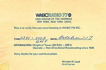
I wish I had been the recipient of this QSL, but it was kindly supplied by Bob Kozlarek WA2SQQ.


BACK TO "JIM'S RADIO ROOM" MAIN PAGE


MORE WABC RELATED PAGES

  • WABC OFFICIAL WEBSITE, Hear WABC on the internet.
  • Allan M. Sniffen's Musicradio 77 WABC The Greatest Top Forty Music Radio Station of All Time! A GREAT WWW tribute by Allan M. Sniffen, to a great radio station. You'll find a virtual tour of the WABC studio, a large collection of airchecks of the most fascinating moments on the air at WABC like what happened during the great NY power blackout or Dan Ingram gets showered with underwear while on the air plus many fabulous letters and stories. I am a lover of all kinds of music, but WABC played an important part of my life in the 60s and 70s when I lived in River Edge, then Norwood, New Jersey after '62. It was the music I danced to and often fell-in-love to. I remember when Harry Harrison, who lived in our neighborhood, dropped in as a guest DJ at our CYO dance. On this page, Allan speaks of my own sentiment. I also listened to WABC during the time I was stationed at K.I. Sawyer AFB in upper Michigan in 1970-1971, the sound of home from afar! I visited the WABC transmitter site in Lodi, New Jersey many times in the 60s. Please visit Allan's page as he pretty much says it all!


Accessed times since January 1, 1997.

Fine Print:
All images are Copyrighted and are provided for your personal enjoyment. Use of these images for commercial purposes including their distribution on CD-ROM or any other media without my permission or that of a contributor is prohibited.

Jim Hawkins