 |
| |
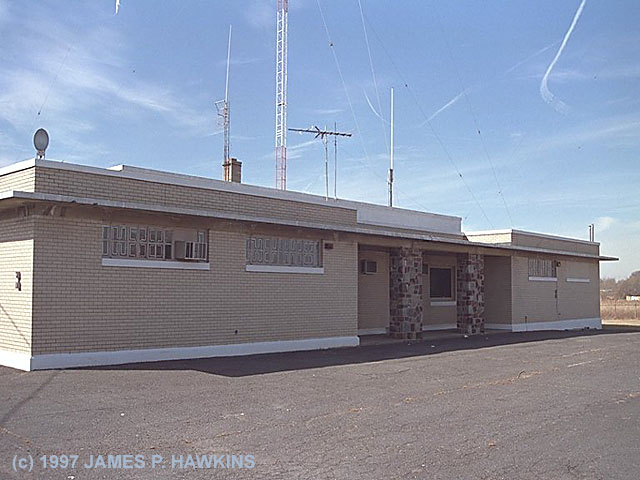
These photos were taken at the WABC transmitter site in Lodi, NJ on February 16, 1997, 31 years after my visit
to the site in 1966, which can be seen on my other JIM'S WABC RADIO 77 Transmitter Page.
The WABC transmitter site has essentially gone through two generations of technological changes between these two
pages. |
 |
 |
 |
The first thing I noticed when I entered the transmitter room was that the new transmitters are much quieter
than the old vacuum tube transmitters, which used enormous blowers to cool the tubes. The roar from the old vacuum
tube transmitters sounded like the engine room of a ship! |
|
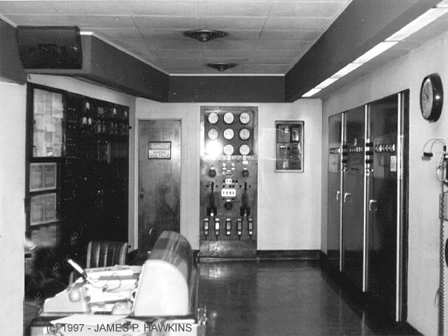
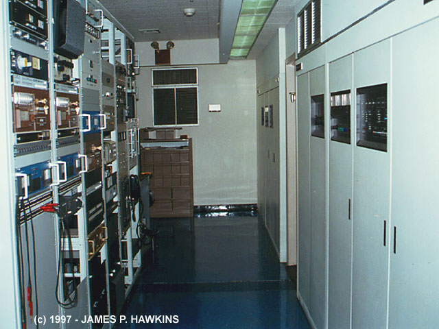
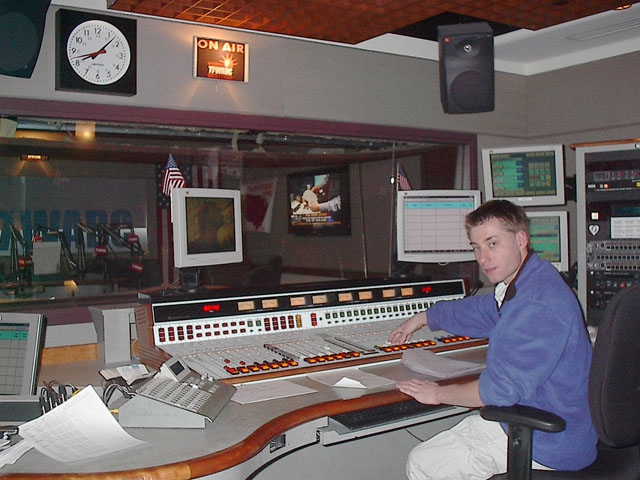
Wide view of transmitter room with 50KW XMTR on right, Power Control panels on left and far end and console in foreground as it was in 1966. |
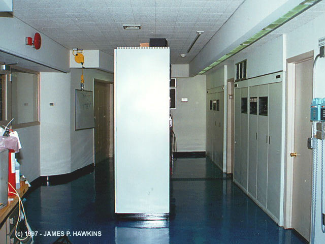
Same view of room in 1997, showing two Harris transmitters that have replaced the old GE Unit. An equipment rack is in the middle of the room and the console is gone. |
|---|
|
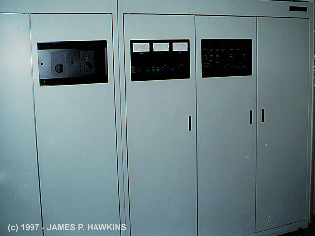
Two Harris Model DX-50 Solid State 50KW Transmitters; one is on the air while one is the standby. |
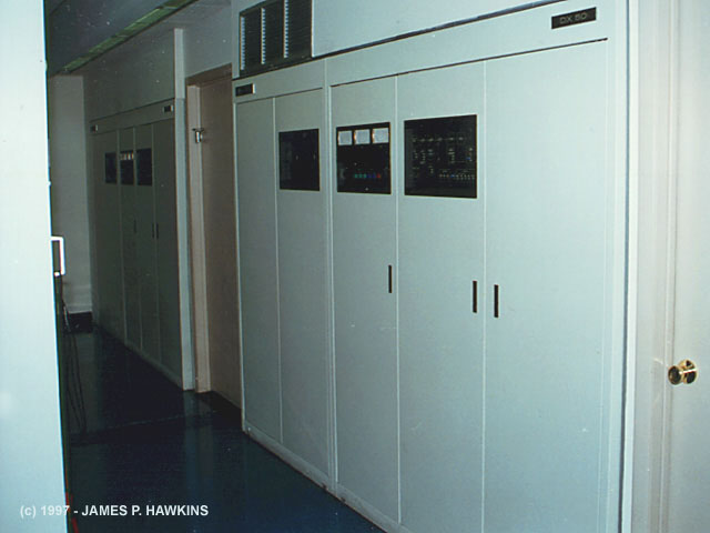
View of the 2 DX-50s on the right and assorted equipment racks on the left. |
A full shot of the older Harris Vacuum Tube Standby Transmitter, which is now out of service. Now replaced with Nautel Units. |
|---|
|
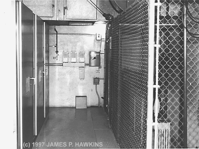
Room behind GE 50KW Transmitter in 1966 showing aisle between transmitter and modulation transformer cage. Note large cooling duct in the rear. |
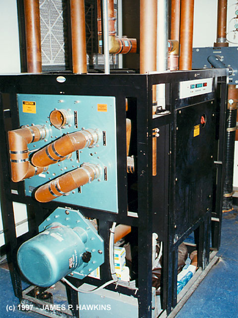
Same room area in 1997 showing rear view of HARRIS DX-50s showing how shallow they are. Everything is contained within those cabinets. There are no huge external transformers, chokes or capacitors. You could probably fit both in an average basement! |
|---|
|
|
| 1010 WINS OFFSITE BACKUP |
| Within the room behind the WABC transmitters is a 10KW Solid State Harris DX-10 Transmitter, which served as a backup for radio station WINS 1010, while they were reconstructing the towers at the WINS site. Once the work was completed at WINS, this transmitter sat dormant, until moved to the WCBS site on High Island, NY, where it is now. (Updated 1/19/2003) |
|
|
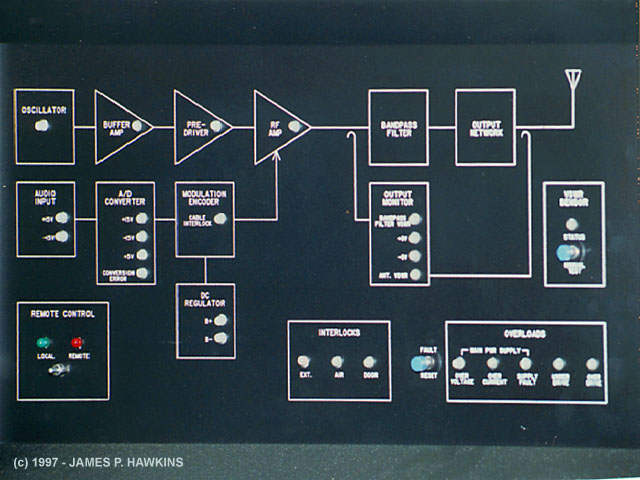
This flow chart is found on the front of the DX-50 with indicator lights within the symbols to show the status of the various major components. |
|---|
|
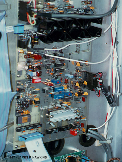
A/D Converter. This is where the audio signal enters the transmitter and is converted to a digital output, the form in which audio is now stored on CDs. A digital audio signal is a stream of binary numbers, each representing a sampled point along the original audio waveform. |
The output of the A/D converter is then fed to the modulation encoder or "integrator" board. You could say this board IS the modulator! This board essentially replaces what would have been a 25+ KW analog high level modulator used in the old vacuum tube transmitters, which is an incredible savings in space and power! |
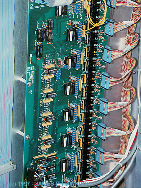
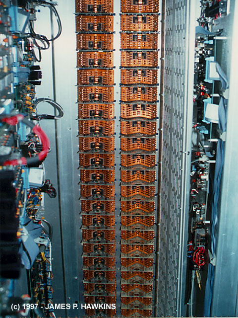
The integrator board controls these stacks of output modules, which make up a total of 64 output modules. There are two sets of these. Rather than a huge tube or pair of tubes delivering the RF output signal in CLASS C, here it is delivered by many modules, each representing a small part of the overall signal. They operate in CLASS D operation, which means that they switch ON and OFF, producing a perfect squarewave. |
|---|
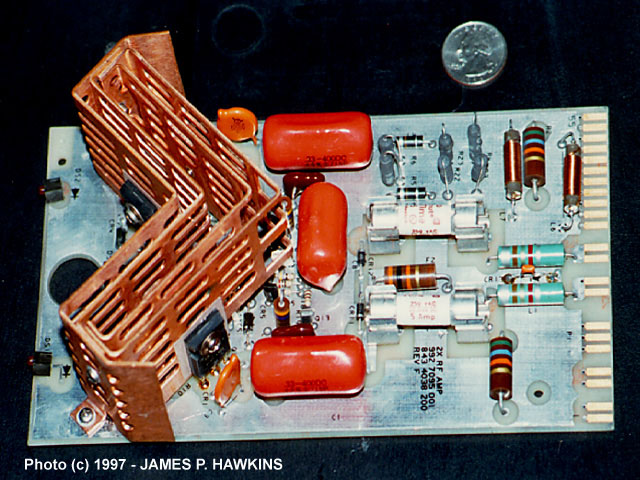
| This is one of the output modules containing 8 output transistors. The module is capable of delivering approximately 1.5 KW output. The input and output is a squarewave whose fundamental frequency is that of transmitter's radio frequency. In the case of WABC, it is 770KHZ. Note the Quarter next to the unit for size comparison. Each has a pair of green lights to show the modulation occurring and a red trouble indication light. |
AMPLITUDE MODULATION (AM) DEFINEDAmplitude modulation is a process which uses the audio signal to modulate or vary the actual power
of the radio frequency signal called the carrier. When no modulation is applied, a steady radio frequency signal
is transmitted, creating a "quiet" spot on your radio dial. When analyzed, the AM signal is quite complex.
It can be shown to be made up of 3 basic components: a steady carrier, an upper sideband signal and a lower sideband
signal, which I will not explain here. AM is susceptible to static interference from lightning, motors, light dimmers,
fluorescent lights, etc. When I am listening to an AM program at home and hear a steady, static "buzz",
I find that it is usually one of the light dimmers in one of the bathrooms. I also remember the buzz of the electric
shavers on an AM station playing while sitting in the barber's chair and hearing a POP when the shaver was turned
on or off. These sources of interference are, themselves, forms of AM signals, which is why they easily infect
your listening pleasure on AM with undesirable sounds. DIGITAL AMPLITUDE MODULATION USED IN THE HARRIS TRANSMITTERSDigital Amplitude Modulation was invented by Harris Senior Scientist Hilmer I. Swanson. In older vacuum tube
AM broadcast transmitters, the carrier was modulated by using an analog modulator, which was essentially the output
of a powerful audio amplifier superimposed on the supply voltage to the transmitter. For reasons I won't explain
here, this type of modulation required an audio signal which was 1/2 the power of the transmitter. That is, for
a 50,000 watt transmitter, you needed a 25,000 watt audio amplifier! That is a slightly simplified explanation,
but it suffices for this comparison. These modulators also required large modulation transformers to couple the
modulation output tubes to the power supply system. RF OUTPUTEach output module is fed with a square wave from the driver section and outputs a square wave. The square
wave output from each module is fed through a coil wrapped around a toroid. A pipe runs through the center of all
the toroids, acting as a secondary transformer winding for all the toroids, which picks up the combined output
of all energized toroids. The toroid filters most of the square wave harmonic components out, leaving an almost
pure sine wave which represents the radio signal. There are other filtering networks before it gets to the output
network in the transmitter, so by the time it gets to the output, the signal is a pure sine wave. COOLINGIn the older transmitter, huge blowers were used to cool the tubes. The air heated by the tubes was typically
around 130 degrees F. With the new transmitters, relatively small air conditioners are used for cooling. Upon putting
my hand in front of the output air vent, the air was barely warm. |
This text is © Copyrighted 1997 by James P. Hawkins and may not be republished on the web or elsewhere, without the written consent of the author.
|
Equipment racks containing, Audio processors, Stereo Processor (not used), Satellite receivers, etc. |
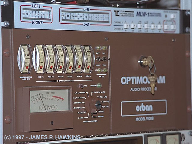
Orban 9100B AM Optimod Audio Processor Unit. This unit conditions the audio signal to sound clearer and stronger at the receiving end. It also compensates for hi and low frequency rolloff on AM receivers. Click on the links for more info on this interesting device. |
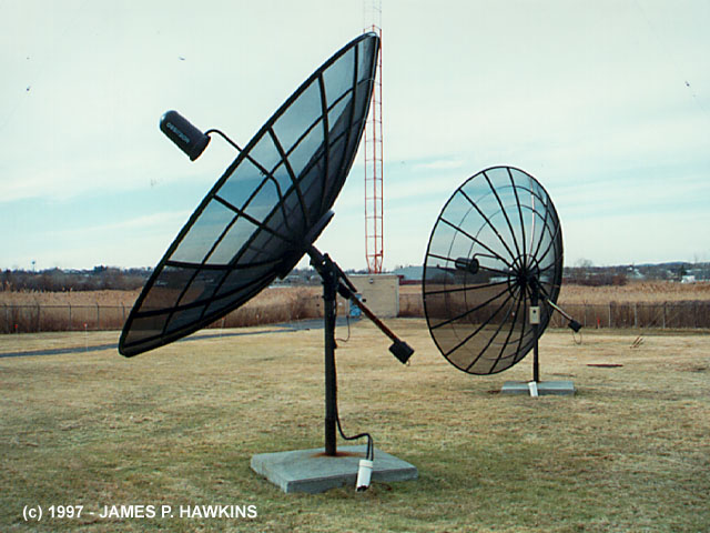
Satellite feed dishes. |
|---|
|
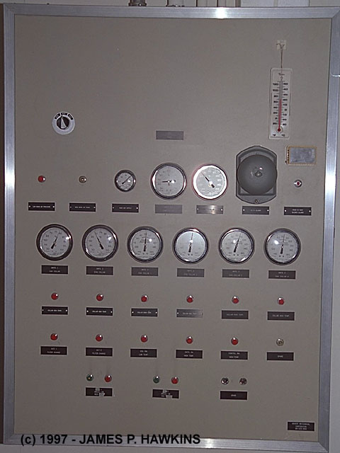
Air cooling metering and control panel. |
|---|
|
Antenna coax switch. |
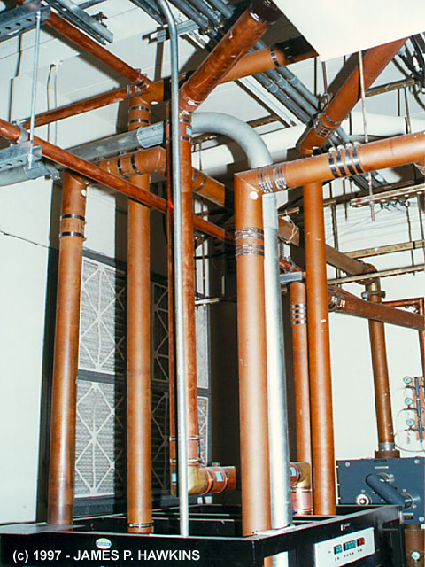
Maze of coax (hardline). |
|---|
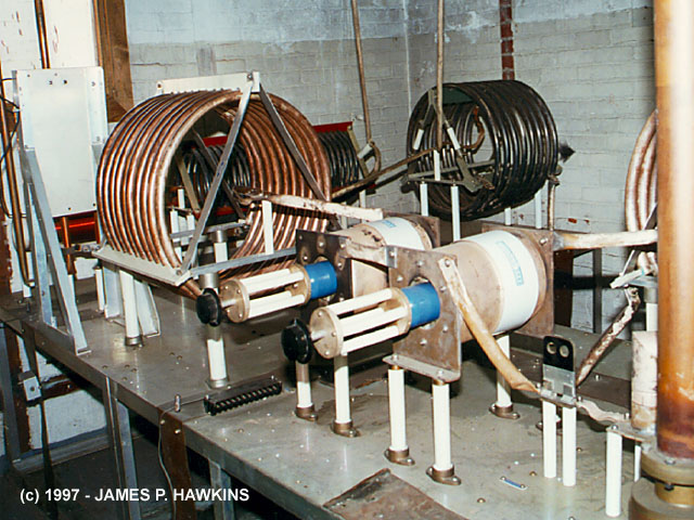
| View of inductors and capacitors inside tuning house located at the base of the antenna tower. Note:
two Jennings vacuum tuning capacitors (with the control knobs on them) which allow tuning for both sidebands. The
dark colored inductor coil in the rear is part of a resonant circuit to filter the WINS signals if the emergency
transmitter and antenna are so used. Due to the strong magnetic fields in the coils, the actual modulation signal
could be heard, making the coils act as speakers as a side effect. Press to hear what coils sounded like when they |
|
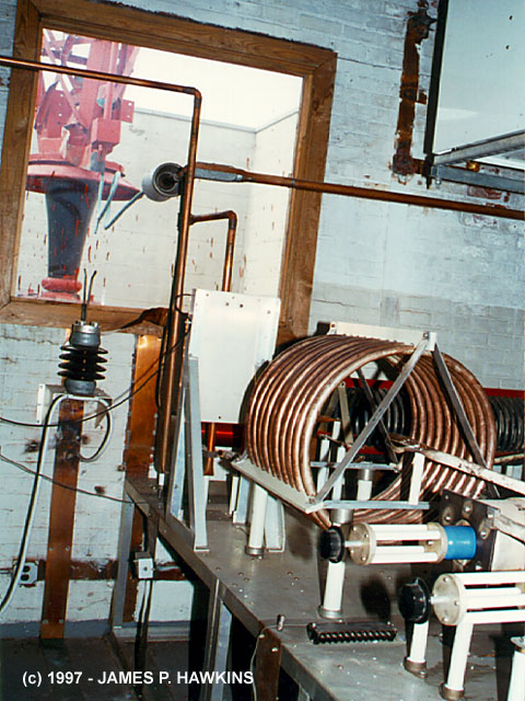
| View of inductors and capacitors inside tuning house leading out to the base of the tower, visible through the window at the far wall. | |
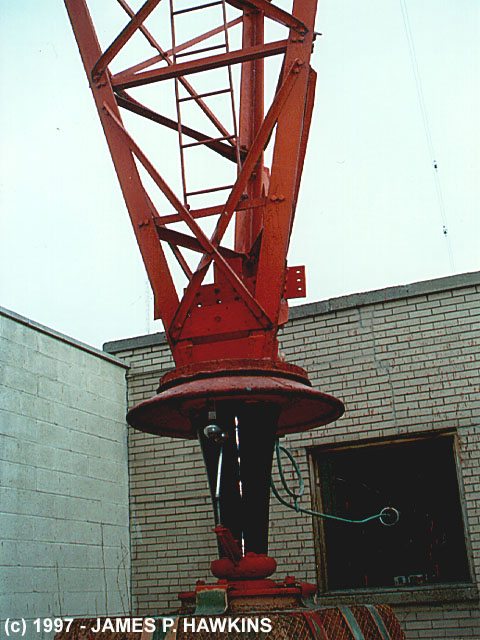
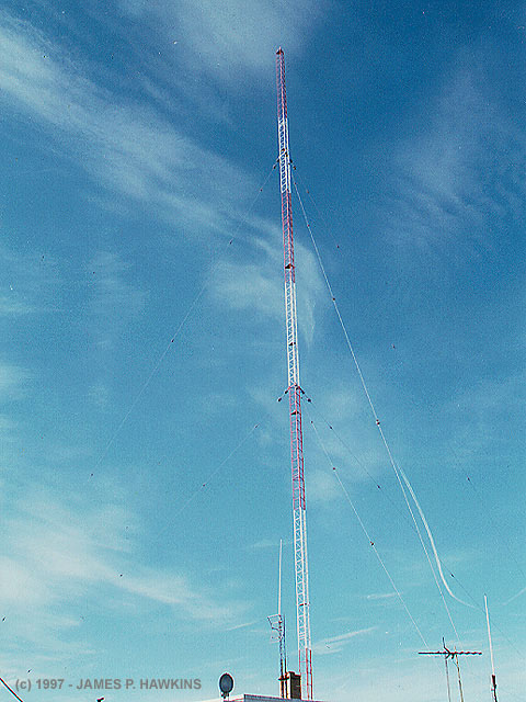
| Huge insulator supporting the entire weight of the 648 ft. tower in addition to wind forces moving the tower. Notice "Johnny Balls" which provide a gap large enough to prevent arcing from the normal 15,000 volt radio signal, but close enough to cause lightning hits to be diverted to ground, protecting the transmitting equipment. | |
| Wider view showing base of tower, fed from tuning house through lucite window. I was told that the antenna impedance is 121 OHMS. |
 |
|
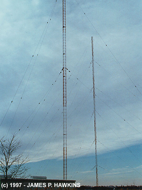
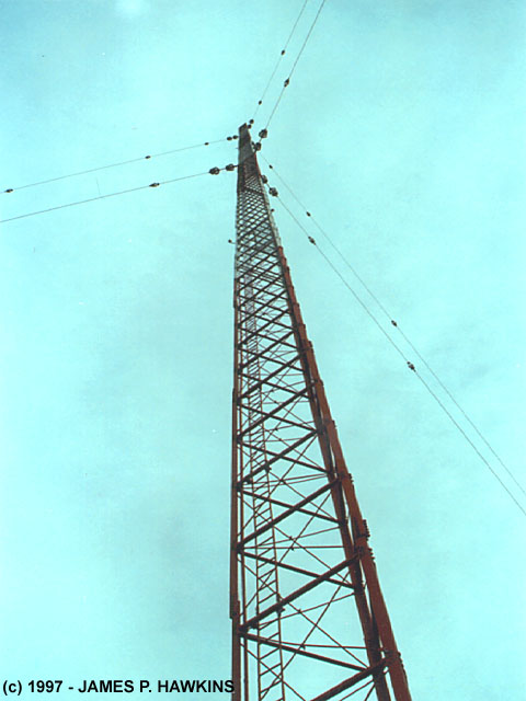
Looking up from base of antenna. |
|
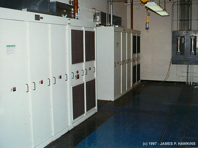
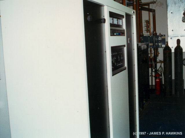
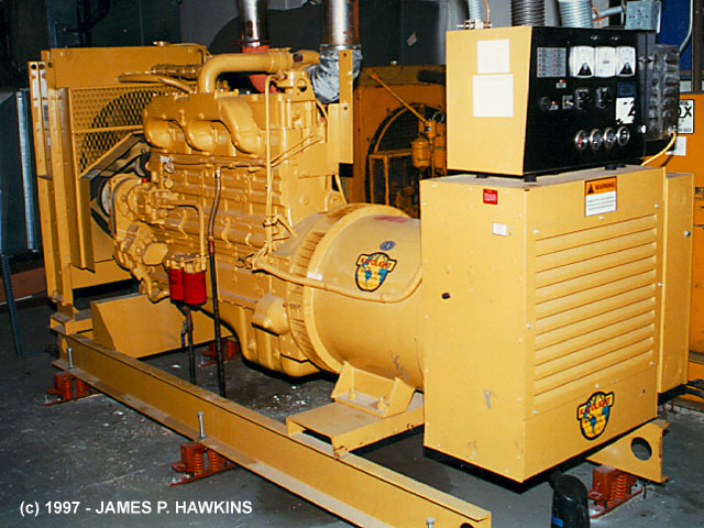
Two emergency generators. On the left is a 250KW generator. On the right is a 150KW generator. |
Full shot of 250KW generator. There's enough fuel and power to run everything in the joint for a month, which is a FEMA requirement! |
|---|---|
|
There are three, 5000 gallon diesel fuel tanks underground to supply the fuel to these generator engines. |
|
| Accessed | times since February 17, 1997. |