|
|
|
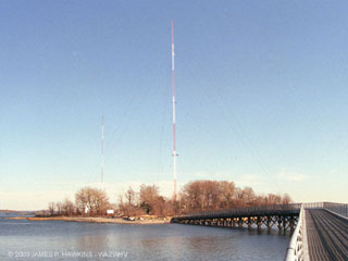
High Island showing bridge from City Island |
|
|
|
High Island showing bridge from City Island |
|
||||
| Accessed | times since January 24, 2003 |
AcknowledgementsThanks to Scott Fybush and Garrett Wollman for inviting and driving me on this trip on 1/15/2003. |
Some BackgroundBoth WCBS and WFAN are owned by Infinity Broadcasting Corp. WNBC, starting out as WEAF, was renamed WNBC
(1946), then WRCA (1954), then back to WNBC (1960). WEAF moved to Bellmore
on the south shore of L.I. before moving to Port
Washington on the north shore. The call letters were changed from WEAF to WNBC in 1946, which later moved from
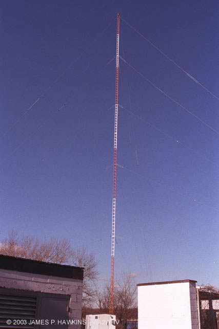
Port Washington (Sands Point), L.I. to High Island in 1963. WNBC radio
vacated the 660 frequency in 1988. WFAN, which was on 1050 at the time, took over that spot. |
|
|
|
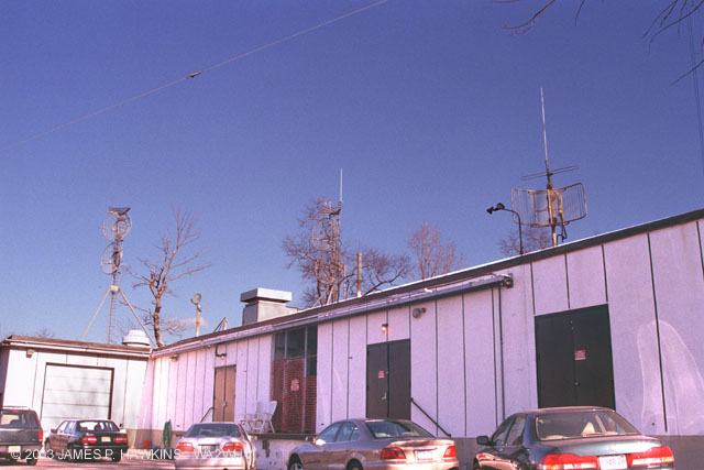
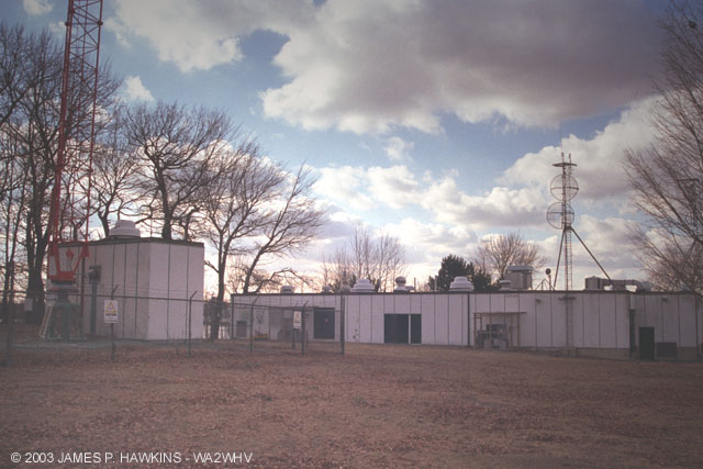
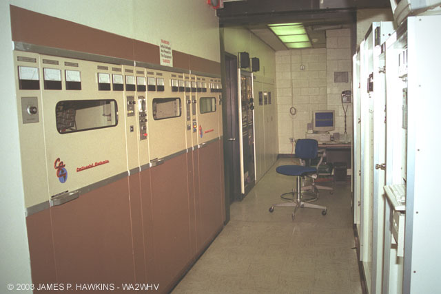
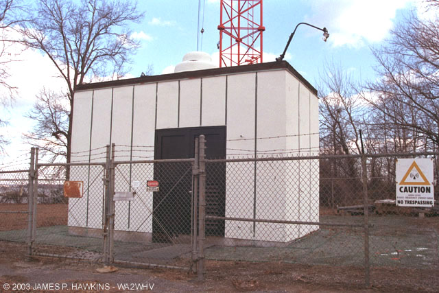
| The transmitter building is divided into two sides for WCBS and WNBC. Each side is separated by a (sort of) breezeway. One must go outdoors to pass from one station to the other. |
|
|
|
|
|
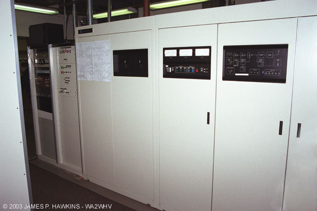
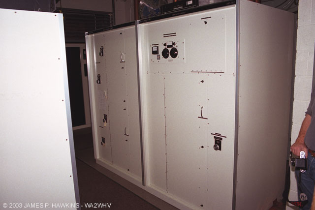
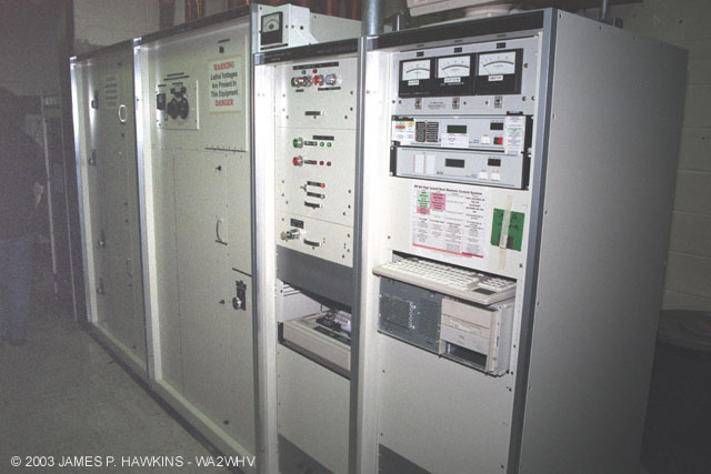
Harris DX-50 Main |
Harris DX-10 |
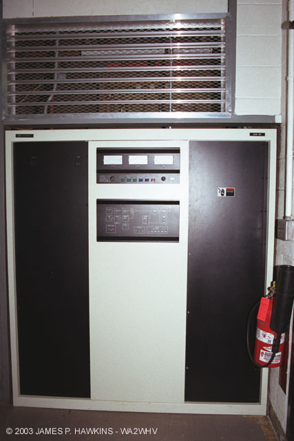
Continental 317C-1 |
|
|
|
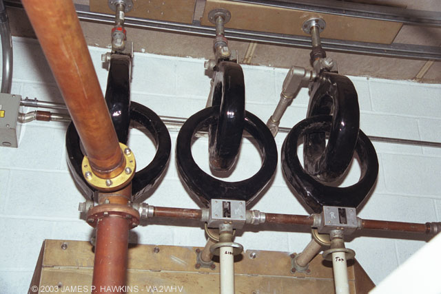
Phase rotator and |
|
|
|
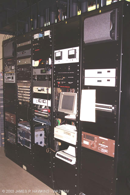
Auxiliary Equipment racks. |
 |
WCBS Transmitter at Columbia Island Photo Supplied by Rick Sedlak |
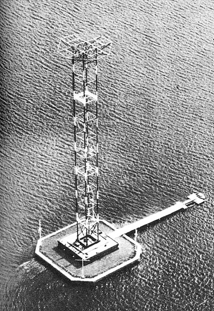 |
WCBS Tower with Capacity Hat on Columbia Island From "The Modern Wonder Book of Knowledge" 1949 |
| Columbia Island was surrounded by a 10 foot sea wall. The tower legs go through the building, but never "touch"
it. They were buffered by insulating grommets. The nautical looking poles at the island corners were designed to
serve as a back up antenna in the event of a loss of tower. The transmitter was built by Federal Telephone of Newark, NJ. --Pete Tauriello, 1010 WINS Morning Traffic Anchor |
|
|
Continental 317C-1 and DX-50 in rear. There is an unseen 5 KW Gates transmitter at the end of the equipment racks on the right side. My understanding is that this was, but is no longer used as an auxiliary transmitter. |
|
|
Phase rotator and matching unit with impedance measurement bridge. This unit is used to match the phase of the outputs of the DX-50, DX-10, and C317 transmitters to the impedance looking into the transmission line. R+jX impedance matching is done to keep sidebands balanced. I was told that this is an uncommon practice at omnidirectional sites. |
before it became WNBC, WRCA, WNBC then WFAN
Bellmore, L.I. (South Shore)
 |
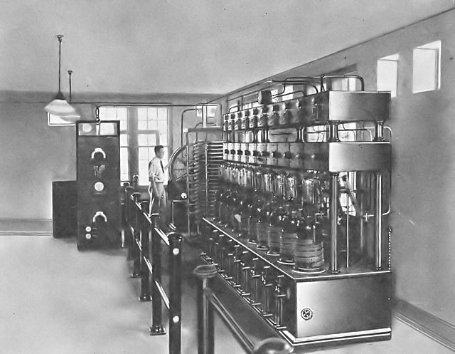
WEAF 50KW transmitter in Bellmore, Long Island, NY View of 32 water-cooled tubes. Water circulates through coils of rubber hose at the base of each tube. Photo: "Radio Telegraphy and Telephony" Duncan and Drew 1929 pp 634. Click for enlargement. |
 |
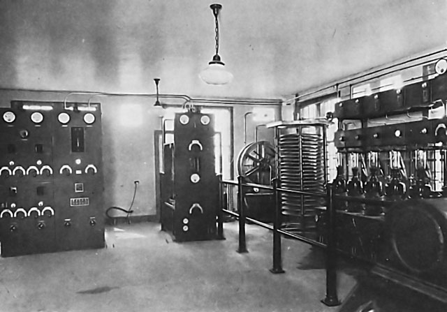
RF Power amplifier and high power tuning system of WEAF's 50KW transmitter at Bellmore. Photo: "Radio Telegraphy and Telephony" Duncan and Drew 1929 pp 632. Click for enlargement. Thanks to Bob Kozlerek WA2SQQ for enhancing these photos. |
 |
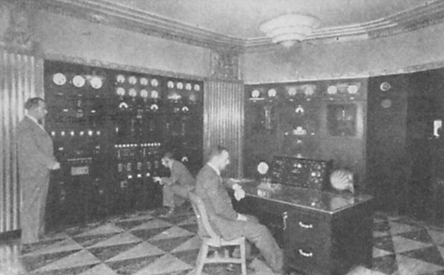
A Later view of WEAF On left is the crystal controlled exciters. Photo: Nationa Broadcasting Company "The Radio Amateur's Handbook" Collins 7th Ed. 1933 |
 |
WEAF transmitter at Bellmore, upgraded to RCA 50B Photo: "Radio News January" 1932 |
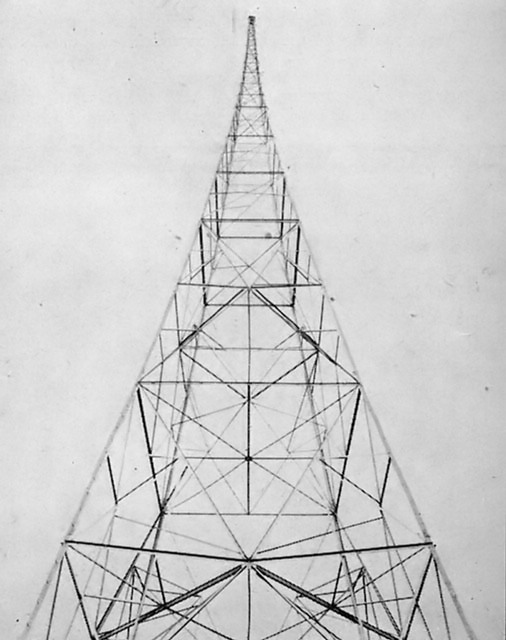 |
WEAF TOWER, Bellmore Source: Radio News January 1932 |
Port Washington, L.I. (North Shore)
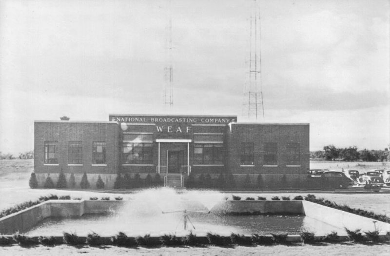 |
WEAF Port Washington Transmitter building 1941 showing water basin in front, used to cool the tubes. Two quarter wavelength antennas are in the background. Photo supplied by John Schneider - "Voices Out of the Fog." |
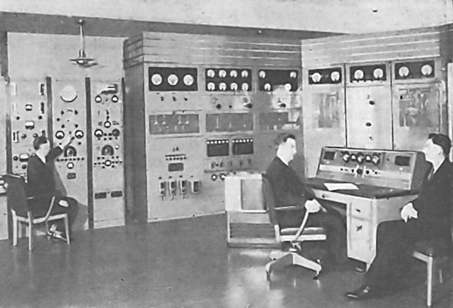 |
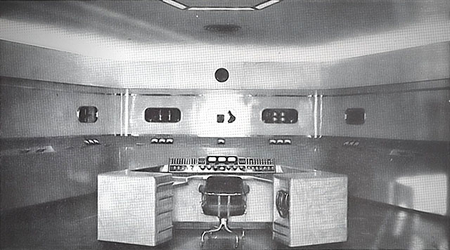
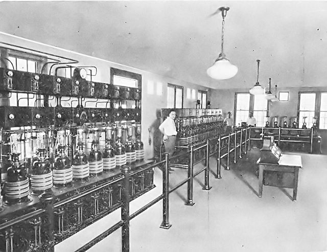
The interior transmitter toom. Photo from Jan 1941 issue of "Radio & Television" magazine. |
|
|
|
|
|
Tuning House |
Diplexer |
Austin Transformers |
| The tuning house contains a diplexer, which combines the signals of WCBS and WFAN, before applying them both
to the antenna. The diplexer/combiner is basically two bandpass filters with outputs tied together to feed the
antenna. The band of frequencies contained in the modulated signal in each case is passed through the filter to
the antenna, but blocked by the other filter so that energy is not passed to the other transmitter. Impedance matching
circuits are placed at the input of each side to match the transmitter to the input of the diplexer. The tower,
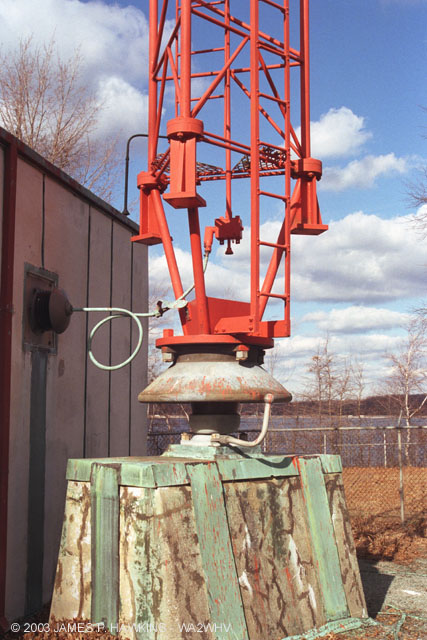
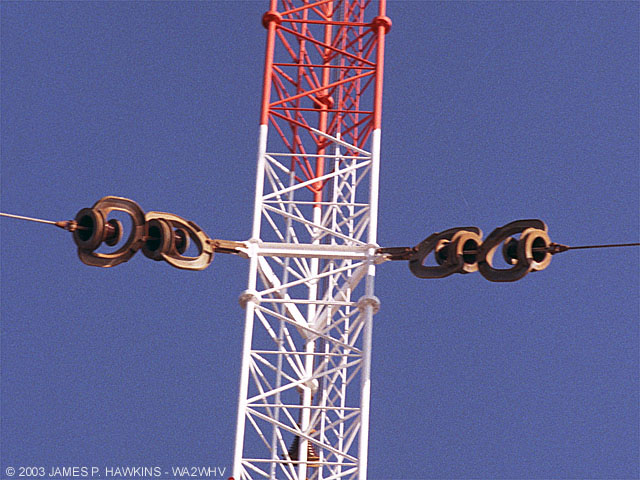
ultimately is handling 100 KW of combined power when unmodulated. The Austin transformers couple the 110 V source to the 110 V line on the tower to light the tower lights, while isolating the RF high voltage of the tower. The interlocking rings are the primary and secondary of the transformer with a gap wide enough for the isolation. |
| Click button to hear sound of WCBS and WFAN in tuning house coils. |
by Jim Hawkins
 |
|
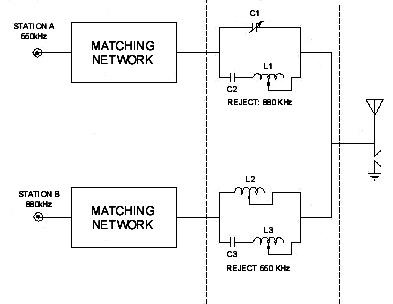
VERY simple example of a diplexer circuit. |
| The above schematic is an example of how reactive components can be arranged to combine the input signals to
the antenna, while blocking signals to opposite transmitters. In the top network C1 and L1 are tuned to antiresonance
to reject 880 KHz, while C2 and L1 are tuned to pass 660 KHz in series resonance. In the bottom network, L2 and
C3 are tuned to antiresonance, blocking 660 KHz, while C3 and L3 are tuned to series resonance, passing 880 KHz.
In the real world, additional components are used to shape the bandwidth and implement more complete attenuation
to the opposite input. Note, that a cross-over network for a high fidelity combination of speakers for an audio system is also a diplexer, except that it works in reverse. Energy is applied to the common node and the networks split (rather than combine) the frequency bandpass for the speakers that handle those ranges. Thus, the diplexer is said to be bilateral. Combiners are less common in the AM broadcast band than they are in television and microwave applications. Combiners are used, for example, on the Empire State Building to combine the signals of many FM and Television stations onto shared antenna arrays. |
|
|
|
|
|
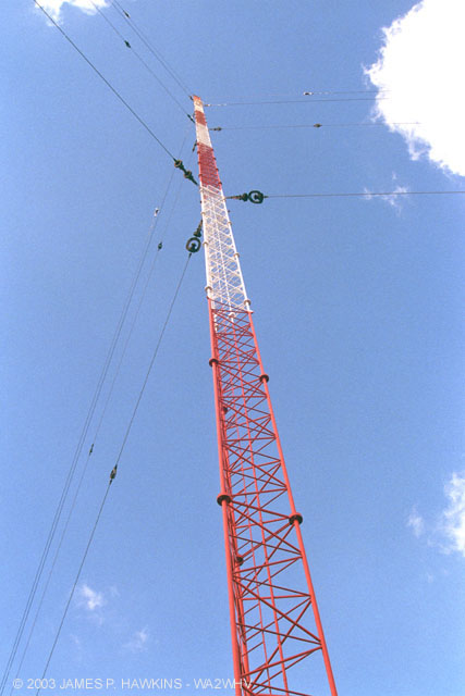
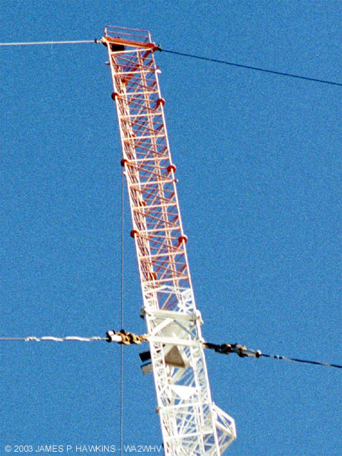
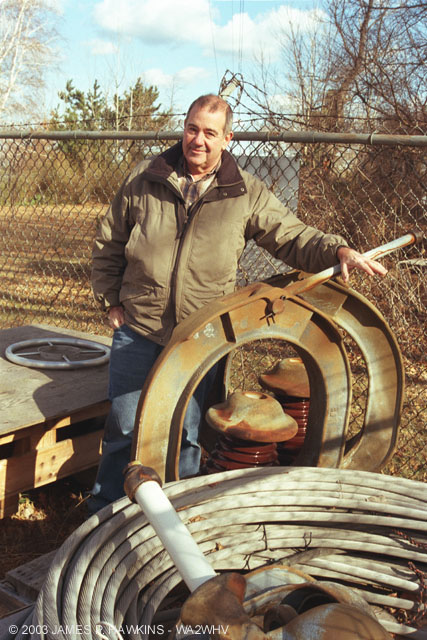
Dick James next to guy insulator assembly to show its relative size. |
|
|
One of the guy wire anchors. |
|
|
R.I.P. Pieces of mutilated antenna resulting from airplane collision in 1967. |
|
|
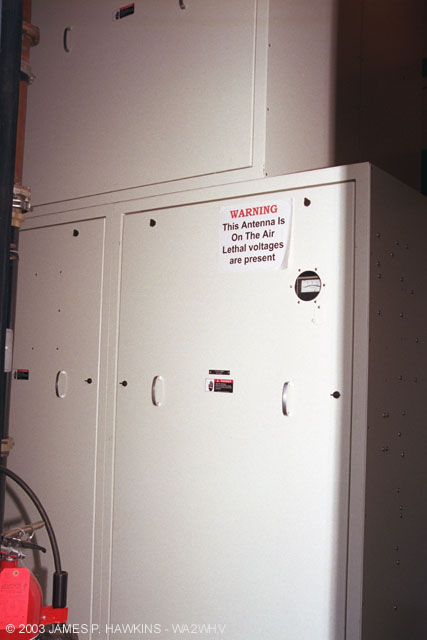
Inward Blowers for the WFAN Continental 317C-1 plate transformer, which is behind the wall. The WCBS 317C-1 is cooled using a closed loop air system. |
|
|
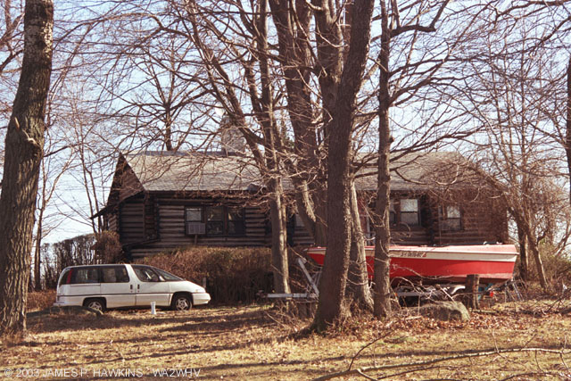
The Island Care Taker lives in this Log Cabin at the southeast end of High Island. |
|
|
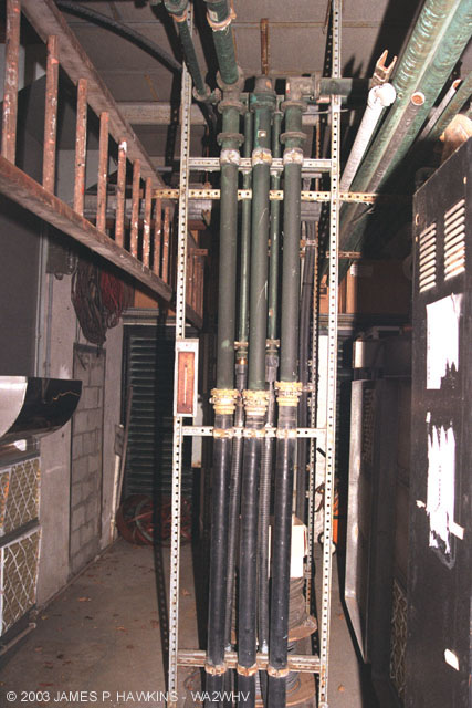
Transmission for WFAN and WCBS lines in center section of the transmitter building. A third is a pressurized spare. The lines run out of the top of the phase rotator units, then down the center to run underground to the antenna. |
AMPLITUDE MODULATION (AM) DEFINEDAmplitude modulation is a process which uses the audio signal to modulate or vary the actual power
of the radio frequency signal called the carrier. When no modulation is applied, a steady radio frequency signal
is transmitted, creating a "quiet" spot on your radio dial. When analyzed, the AM signal is quite complex.
It can be shown to be made up of 3 basic components: a steady carrier, an upper sideband signal and a lower sideband
signal, which I will not explain here. AM is susceptible to static interference from lightning, motors, light dimmers,
fluorescent lights, etc. When I am listening to an AM program at home and hear a steady, static "buzz",
I find that it is usually one of the light dimmers in one of the bathrooms. I also remember the buzz of the electric
shavers on an AM station playing while sitting in the barber's chair and hearing a POP when the shaver was turned
on or off. These sources of interference are, themselves, forms of AM signals, which is why they easily infect
your listening pleasure on AM with undesirable sounds. DIGITAL AMPLITUDE MODULATION USED IN THE DX SERIES HARRIS TRANSMITTERSDigital Amplitude Modulation was invented by Harris Senior Scientist Hilmer I. Swanson. In older vacuum tube
AM broadcast transmitters, the carrier was modulated by using an analog modulator, which was essentially the output
of a powerful audio amplifier superimposed on the supply voltage to the transmitter. For reasons I won't explain
here, this type of modulation required an audio signal which was 1/2 the power of the transmitter. That is, for
a 50,000 watt transmitter, you needed a 25,000 watt audio amplifier! That is a slightly simplified explanation,
but it suffices for this comparison. These modulators also required large modulation transformers to couple the
modulation output tubes to the power supply system. RF OUTPUTEach output module is fed with a square wave from the driver section and outputs a square wave. The square
wave output from each module is fed through a coil wrapped around a toroid. A pipe runs through the center of all
the toroids, acting as a secondary transformer winding for all the toroids, which picks up the combined output
of all energized toroids. The toroid filters most of the square wave harmonic components out, leaving an almost
pure sine wave which represents the radio signal. There are other filtering networks before it gets to the output
network in the transmitter, so by the time it gets to the output, the signal is a pure sine wave. OBSERVATIONIf you could stop the modules from putting out a squarewave at the carrier firequency and set the outputs to a steady DC voltage, the DX-50 would simply be a high powered D/A converter/power amplifier, one that converted low power digital, to high powered analog output! COOLINGIn the older transmitter, huge blowers were used to cool the tubes. The air heated by the tubes was typically
around 130 degrees F. With the new transmitters, relatively small air conditioners are used for cooling. Upon putting
my hand in front of the output air vent, the air was barely warm. |
|
|
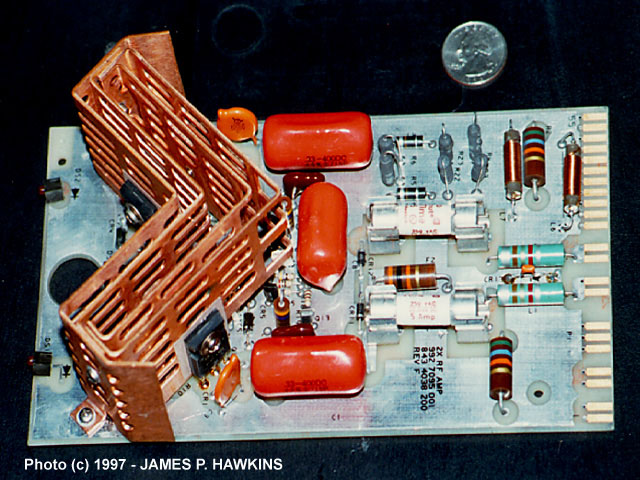
This is one of the output modules containing 8 output transistors. The module is capable of delivering approximately 1.5 KW output. The input and output is a squarewave whose fundamental frequency is that of transmitter's radio frequency. In the case of WCBS or WFAN, it is 880KHz or 660KHz. Note the Quarter next to the unit for size comparison. Each has a pair of green lights to show the modulation occurring and a red trouble indication light. |
|---|
| In 1913 Nora and Jack Beatty lived on High Island in a two-story, wooden farmhouse, renting out campsites. In
1925, the Miller family purchased the island and built 20 bungalows there, providing a summer resort for about
100 people. Before a footbridge was constructed to connect it to City Island in 1928, residents accessed the island
by walking on a sandbar at low tide or took a boat at high tide. Residents began to park their cars on City Island,
transporting furniture, groceries and other necessities to the island by wagon. About eight of the families who leased bungalows became attached to the island and decided to make it a permanent home. In 1960 they unsuccessfully fought a zoning change that enabled WCBS and WNBC ultimately to buy the island for their transmitter facilities. A few years later, the bungalows were razed, the trees were cleared, the bridge was widened, and the transmitter facility was built. A remaining log cabin is the last vestige of the old community, which is now owned by a care-taker paid by WCBS and WFAN to maintain the island. The island is regrown with a variety of trees and brush and shores of the island are rocky. Reference: "The Other Islands of New York City - A Historical Companion" by Sharon Seitz & Stuart Miller, © 1996 |
© Copyright MMIII James P. Hawkins
BACK TO "JIM HAWKINS RADIO & BROADCAST TECHNOLOGY PAGE