|
|
|
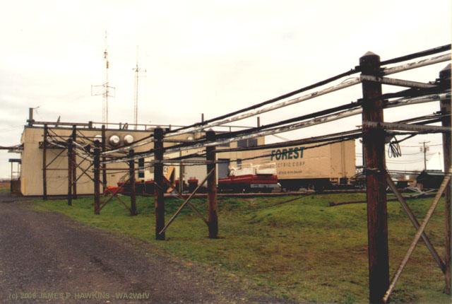
WBBR towers and transmitter building. Located |
|
|
|
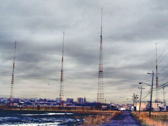
WBBR towers and transmitter building. Located |
Google map location marker.
| This transmitter site was constructed in 1968 for WNEW AM, when they left their old
transmitter site in Kearny, NJ. WNEW used this site from 1969 to 1992, when WNEW broadcasts came to an end. I remember, traveling down the eastern spur of the NJ Turnpike every day when I was attending school in NY and watching the towers progress each day as I drove by. I had no idea what they were at the time. The antenna system is composed of 4 towers: 1 main 435' tower (#1), which is used exclusively during the daytime and 3 smaller towers (#2, 3 and 4), each 235' tall added in to create a directional pattern at night. |
Thanks!My sincere gratitude goes to René Tetro - N2GQL, CE, for the excellent and informative tour and also
thanks to |
CONTENTS |
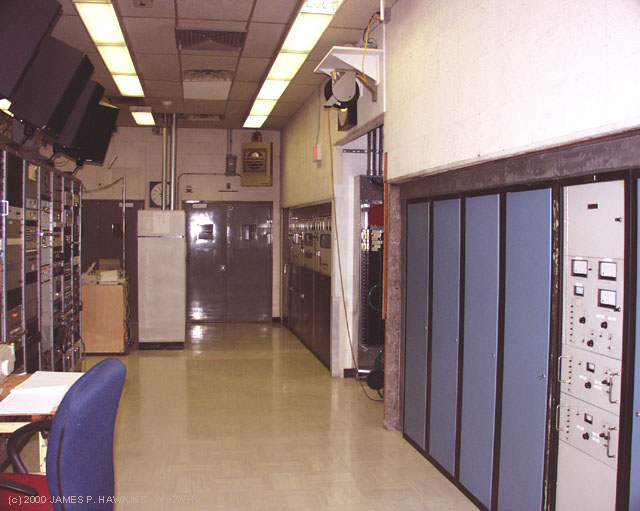 |
The Main Transmitter area showing auxiliary equipment racks on the left and the main and backup 50KW transmitters on the right. |
| The transmitter was installed by Bob Janney, who was WNEW's transmitter engineer in those days (and is still
WBBR's transmitter engineer), and Al Kirschner, WNEW's chief engineer. I came on the scene later in Sept. 1990 as Al's assistant CE and took over the CE position under Bloomberg. |
 |
Main Nautel 50KW Model AMPFET-50 solid state transmitter with Pulse Width Modulation (PWM) on the collectors. Installed in 1989 while the site was still WNEW AM. |
|
|
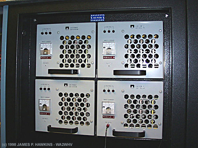
Nautel transmitter control and meter panel. The RF power amplification is distributed among 4 racks of modules, two to the right and to the left of the control rack. The switched metering is designed to measure the supply voltage and current to each of the four racks separately. The RF output meter shows about 52 KW output from the transmitter. (click on the image for a close-up) |
The modules below were photographed at WMCA, but are the same modules used in the AMPFET 50.
|
|
Each rack is composed of smaller RF amplifier modules, each rated nominally for 1.4 KW. The modules each contain, PA/Modulator Assemblies and are all modulated equally. The outputs are combined to obtain the full 50+ KW. If a module should fail, it can be removed and replaced with another module while the transmitter is operating, causing only a brief power reduction during the change. Each module is broken down further into 3 boards. |
|
|
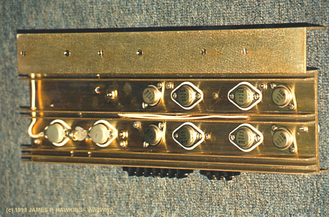
Top of individual transmitter module board. There are three of these boards per module, designated as 'A', 'B'
and 'C'. Three indicator lights on the parent module indicate if a board has failed. |
|
|
Flip side of transmitter module board. These boards "buzz" with the sound of the audio modulation. |
|
|
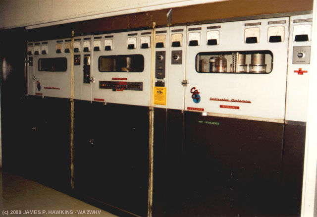
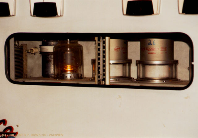
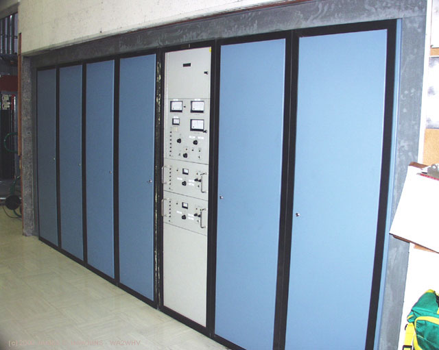
Continental Electronics 317-C1 50KW all tube Screen Modulated, modified Terman Doherty Transmitter, installed in 1969. Basically a Doherty amplifier with modulated screens. W.H. Doherty was responsible for early successful linear amplifier designs in the 1930s. An oscilloscope is on one of the panels to help adjust the phase relation between the "peak" and the "carrier" tubes. |
|
|
Close-up of window showing driver tubes. |
|
|
|
|
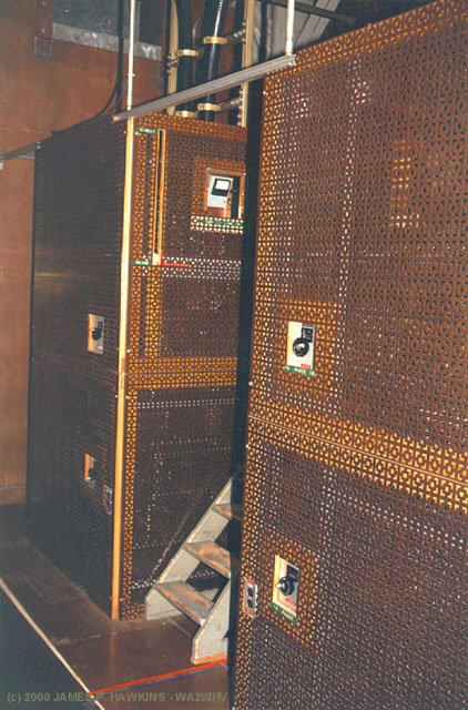
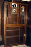
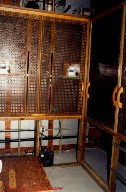
Copper Phasor cages. |
|
|
|
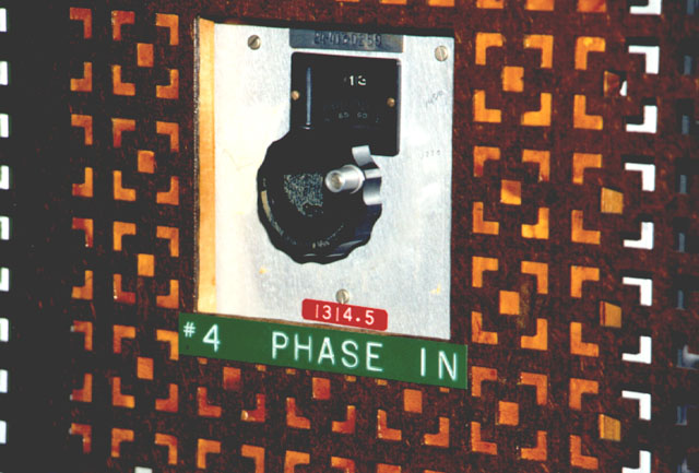
| Close-up of phasor control, showing heavy copper mesh. |
|
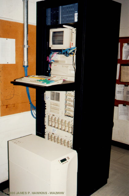
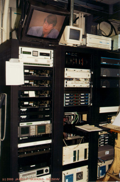
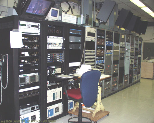
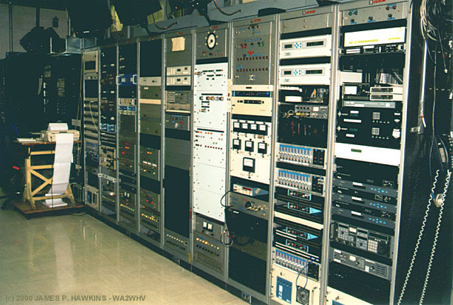
Auxiliary Racks |
|
 |
 |
|
Left View |
Right View |
The auxiliary racks contain, speech processing, remote control, satellite receivers, transmitter control and other additional equipment.
|
|
This is a complete automation system, including server, program logs, and audio playback for WBBR and the two Bloomberg Radio Networks. The system mirrors the automation system in New York. When the news people submit their reports and programs to the automation system in NYC, it is simultaneously submitted to the appropriate system in Carlstadt. If NYC goes down for whatever reason (power failure, etc), we can switch to the Carlstadt system for broadcast. |
|
| The idea is to keep us up and running until we can get news personnel to the transmitter site to begin filing new reports. The program switcher at the transmitter which would allow us to switch systems can be controlled via the Burk and Moseley remote control systems, which can be operated via touch-tone phone in an emergency. -- Rene' Tetro |
||
|
|
Bloomberg TV link equipment. |
| Aside from the radio, Bloomberg has several TV networks, all of which are formatically similar (primarily business
news), but are geared to various locales (NY Metro, the United States, Western Europe, the Pac Rim, and Brazil). The US network is on both Direct-TV and Dish Network, and is also run on USA Cable network between 5AM and 8AM. While most of our program channels are delivered to the various uplink sites via fiber, the Satellite receivers and several of the dishes at the transmitter are used by to downlink backhaul feeds and reports for later broadcast (on the scene reports, etc). No dieo processing, per se, is done at Carlstadt: anything of that nature is handled in New York. -- Rene' Tetro |
|
|
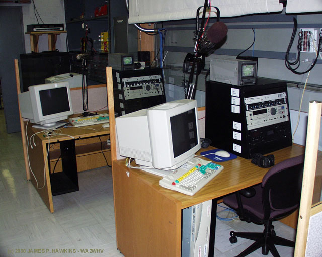
A disaster recovery site studio is provided at the transmitter site. This is used for reporters to file broadcasts as in the New York studio. |
|
|
A small studio located in the office is used to "go live" from Carlstadt, should the need arise. Photo shows mixer board, RE27 Mike and other equipment. |
| WBBR has served for the past two seasons as the "backup station" for the NJ Nets. In other words,
we broadcast the Nets games when WOR-AM had programming conflicts such as a Rutgers game. This small studio in the office was used to broadcast the Nets games. The backhaulfeed would be sent us from Continental Arena via ISDN and we would insert commercials, playback for replay, phone calls during the post game show, etc. -- Rene' Tetro |
|
|
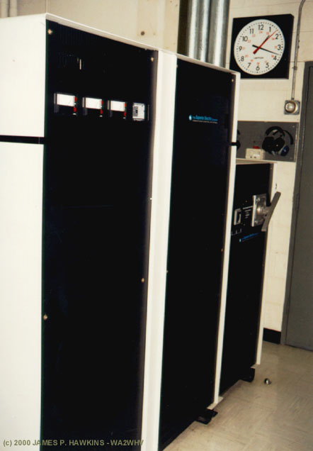
Three Phase Power
|
|
|
|
Power conditioner meters showing 3 phase 480 volts. |
|
|
|
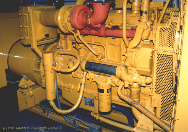
Emergency 500 KW Generator |
|
|
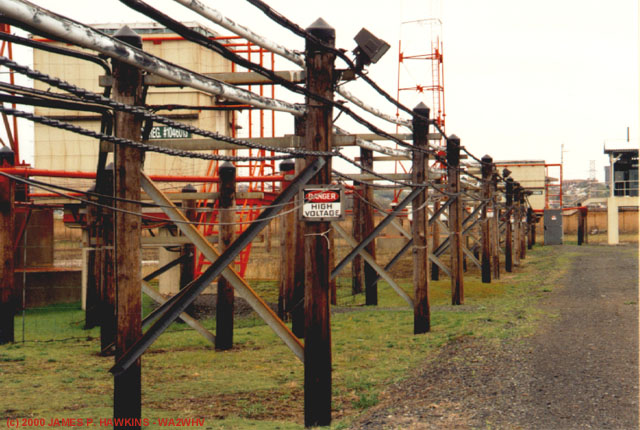
Transmission and Control Lines
|
|
|
Transmission and Control Lines to the antenna tuning houses. |
|
|
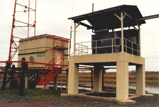
Antenna tuning house and emergency generator at tower #4. From geologist studies. These facilities stand off the ground above the highest water level from the last 500 years. |
| The tuning house at tower #4 is the only one that contains an auxiliary transmitter and generator. All four
tuning houses are air conditioned in the summer and heated in the winter to minimize the environmental impact on the equipment. |
|
|
Antenna tuning system in copper mesh housing. |
|
|
Auxiliary Nautel XL-12, 12 KW transmitter in the antenna tuning house at tower #4. |
|
|
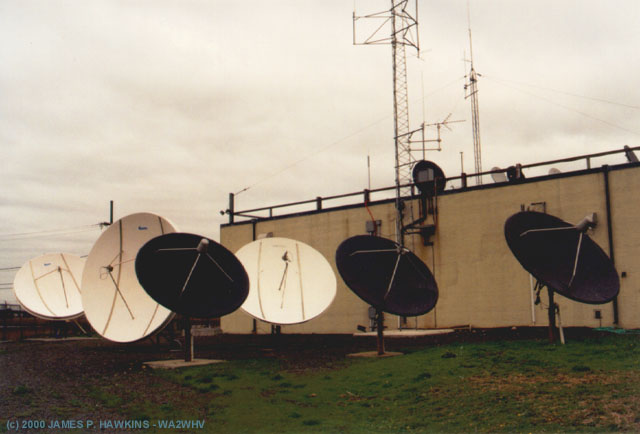
| All but two of the dishes are used for television and are completely steerable. The one dish used for radio
is fixed, looking at Satcom C5, which is the bird Bloomberg Radio Network is on. We use Starguide as our satellite provider. The other radio dish looks at Galaxy 6 for NPR, BBC, and other services. There are also several smaller dishes on the roof that are used for such things as Associated Press (wire and radio), AFP (the French Press Agency), and other data services. The reason we have so many is because we are taking so many different feeds from different sources and birds, some permanently, others intermittently. The four steerable television dishes enable our video people to take in several feeds at once. They also provide a semblance of redundancy. -- R.T. |
|
|
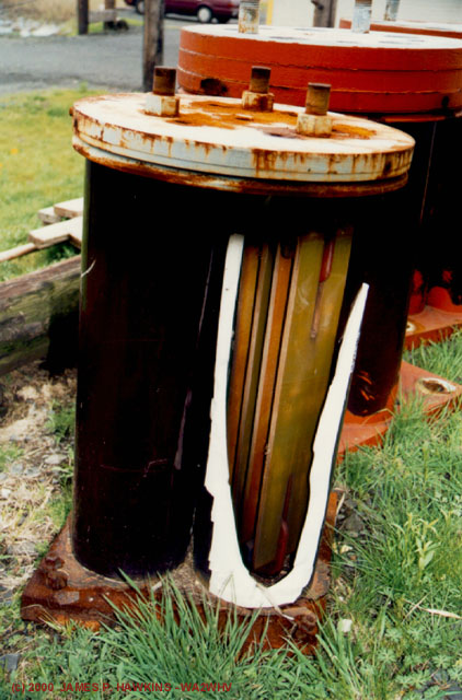
Defective tower base insulators which have been removed. Boat used to gain access to parts of the system when the water level is too high. |
|
|
A broken insulator which shows that these insulators are not solid porcelain. They are hollow, filled with oil and some other contraption. |
|
|
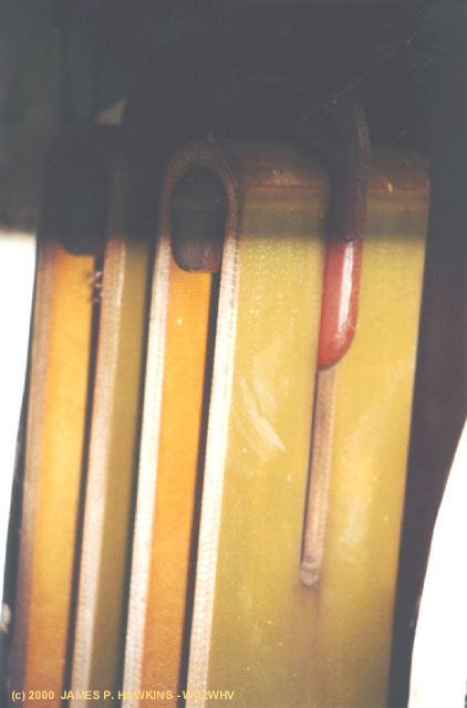
Here is a close-up of the "stuff" that is inside the insulator. How it works, I do not know. |
| Accessed | times since May 10, 2000. |
Fine Print:
All images are Copyrighted and are provided for your personal enjoyment. Use of these images for commercial purposes
including their distribution on CD-ROM or any other media without my permission is prohibited.
Contact: Jim Hawkins