|
JIM HAWKINS' WLWTransmitter Page WLW 1997 Tour Video
|
|
JIM HAWKINS' WLWTransmitter Page WLW 1997 Tour Video
|
Western Electric 7A |
|
70 year old Western Electric 7A
|
CONTENTS
|
THANKS!My sincere gratitude goes to Engineering Manager, Paul Jellison - WD8KMX, who spent hours
giving me a tour of the site. I am also grateful to Jacor VP of Engineering, Al Kenyon, for responding to my Usenet
posting, giving me the go-ahead for this tour; and for additional technical information! I am also very greatful
to Mr. Randy Michaels, CEO of Jacor, Inc. for his influence in the preservation of this site. Thanks also to Pete
Tauriello, Shadow Traffic reporter for WINS 1010, NY, for telling me that WADO also used a Blaw-Knox tower. (The
WADO tower has been replaced on 10/17/1999.)
Thanks to J.T. Anderton, VP/Managing Director of Duncan's American Radio, for his informative piece on Blaw-Knox
towers and other WLW information. John Byrns sent me a good portion of the technical operation details of the 500KW
transmitter. Thankyou, John, for your important information. Thanks, also to Barry Mishkind and John Price who
wrote articles on WLW (See other WLW related pages at the bottom). |
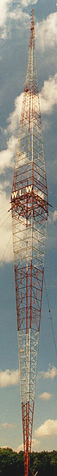
The transmitter plant is located on Tylersville Road off I-75 just beyond the now defunct VOA Bethany Site about 23 miles north of Cincinnati. The single, omnidirectional, double diamond-shaped halfwave tower is now 747 feet high. It weighs 135 tons and was built by Blaw-Knox.
WYGY FM, owned by Chancellor broadcasting, has antennas on the top of the WLW tower. The WYGY transmitter facility is in a separate building, which we did not visit. They use a Continental and Harris 20 KW transmitter in main and standby service. |
 |
|
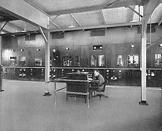
A 1930s picture of the 500KW transmitter. More of these pictures can be seen in the brochure
gallery page. |
|---|
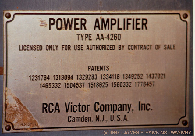 |
Boilerplate attached to one of the rear doors of the 500KW transmitter. The rig is credited as RCA Serial #1,
but was actually a joint effort. RCA was responsible for the overall design of the transmitter, GE was responsible for the RF section and Westinghouse was responsible for the control systems. |
| Before the 500 KW transmitter was walled off in 1975 into a shallow room, it was visible from a broad area in the plant. It is now more difficult to photograph. The room is also used as a temporary storage area for equipment and other station property. The transmitter itself is physically huge, composed of chambers with windowed doors on top of a catwalk. Below the catwalk are other panels with metering and controls. On either side of the transmitter, one can walk up steps to the catwalk or straight ahead to the rear of the cabinet, where there are steps back down to the floor. The back of the transmitter is deceiving. It looks like an ordinary wall with double doors which resemble closet doors. On the other side of the hallway are windows to the back of the building. The total height of the transmitter is 15 ft tall by 54 feet wide (about 2 1/2 times my height)! |
|
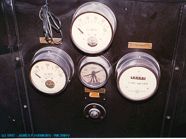
|
|
|
|---|---|---|
|
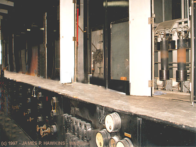
Wide view of 500KW transmitter showing catwalk. (Equipment stacked on catwalk was removed.) |
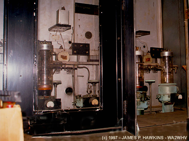
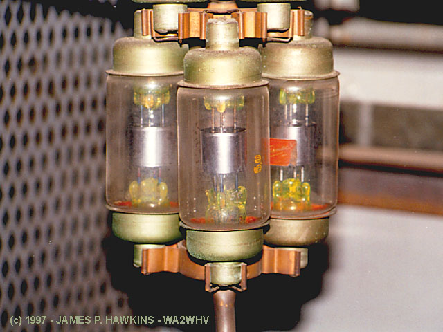
Open door view of water-cooled transmitting tubes in one of the chambers. These tubes are 5 feet high. The bottom of the tubes are metal sheaths, through which the cooling water was run and then pumped outdoors to fountains in a cooling pond in front of the plant. |
View of two cabinets showing tubes. |
|
|
|
|
|---|---|---|
|
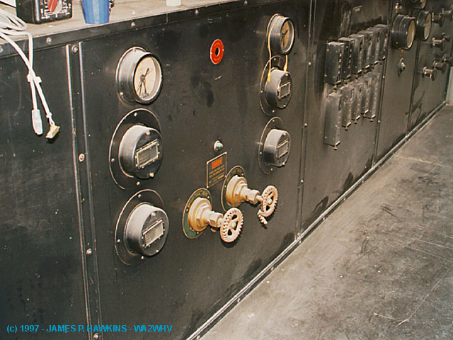
Panel below catwalk. |
Panel below catwalk shows what appear to be water cooling valve controls. |
General view of transmitter. (Some retouch work was done to eliminate equipment store on the catwalk and floor.) |
500 KW TRANSMITTER DESCRIPTION IN A NUTSHELL
|
|
|
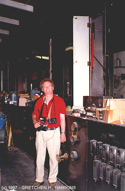
Here I'm standing in front of the big, 15 foot tall transmitter. |
|
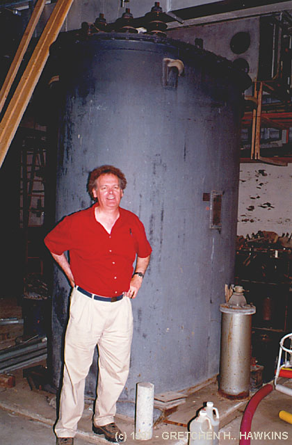
Here I'm dwarfed by a modulation transformer for the big transmitter (in the basement). I'm 6 ft tall. This is one of two of these transformers that were originally used, each weighing 35,700 lbs, filled with 725 gallons of oil. The oil has been drained from this transformer due to PCBs. |
|---|---|---|---|
|
|
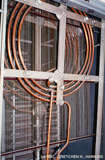
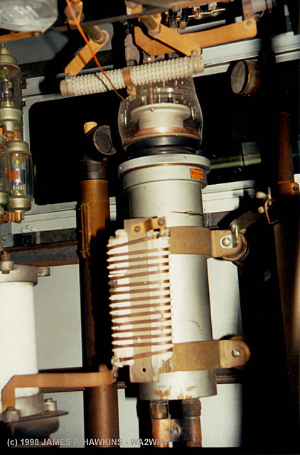
View of link coupled output coils with Faraday shield and tank circuit capacitor (looks like a baking rack) in the back. Tuning is accomplished by changing the inductance of the coil. Loading is accomplished by moving the outer coil closer or farther away from the inner coil. This is all mechnically coupled to controls in the front of the transmitter. |
|
Part of the switching and relay system for the 500KW transmitter (in the basement). |
Click For MORE PICTURES OF THE OLD 500KW RIG
DIRECTLY FROM THE MANUAL
|
|
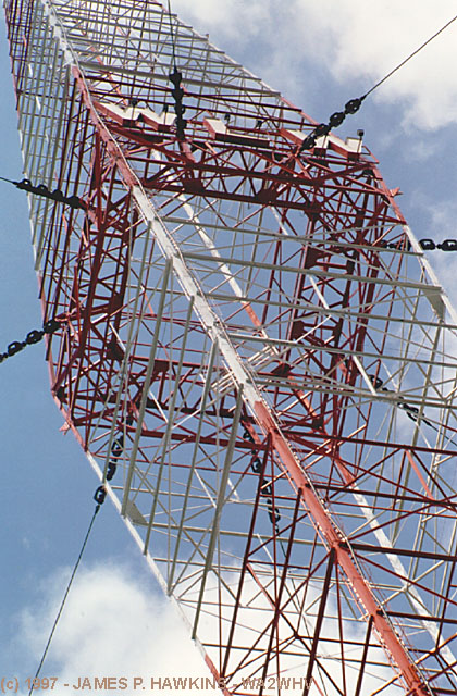
Dramatic shot of the famous Blaw-Knox, diamond shaped tower, looking up to the center of the tower. The "WLW" sign on the tower is approximately 11' X 35' wide. Please see the note from Mr. J.T. Anderton, who kindly supplied additional information on this tower and WLW. |
|---|---|
|
|
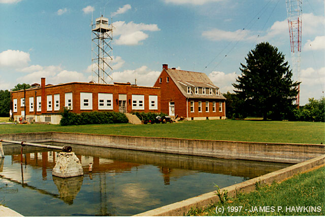
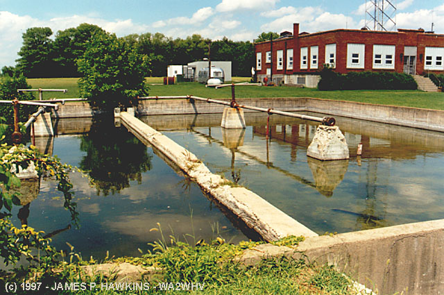
Full view of pond once used to cool the transmitter tubes. Water was sprayed into the air as fountains. Frogs and other life now make their home in this pond. |
|
|
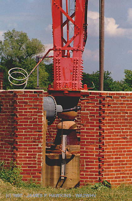
View through wall around base of tower showing insulators which support 900,000 lbs! |
A Note From J. T. AndertonVP/Managing Director of Duncan's American RadioIn addition to a lifelong interest in AM tower sites and coverage, I have been fortunate to have had the
opportunity to do more than two years of research in the internal technical file room of the FCC, to gather technical
data for my series of coverage map atlases, published by Duncan's American Radio. In addition, I visited more than
2,500 stations in all parts of the country during an 11-year stint as a regional manager for the NAB. I have also
photographed more than 1,000 tower sites over the past 20 years. I have talked with radio people and engineers
in all parts of the country, and also have had the chance to cross-check the heresay and folklore at the FCC. Given
that these towers are so unique, I'm fairly confident that if there are more, I would have come across them by
now. WSM, Nashville (650) 800' WLW, Cincinnati (700) 739' WBT, Charlotte, NC (1110) 3 in directional array, 428' each WFEA, Manchester, NH (1370) Taller of two towers in directional array, 350'(second tower is 199') WBNS, Columbus (1460) WHO in Des Moines had one until the late 1940's, when it was replaced at the same site by the existing uniform
cross-section tower. The bottom two-thirds of the old WHO tower was moved to the rear of an Iowa State Police station
in Des Moines for use as a communications tower. |
|
|
|
|---|---|
|
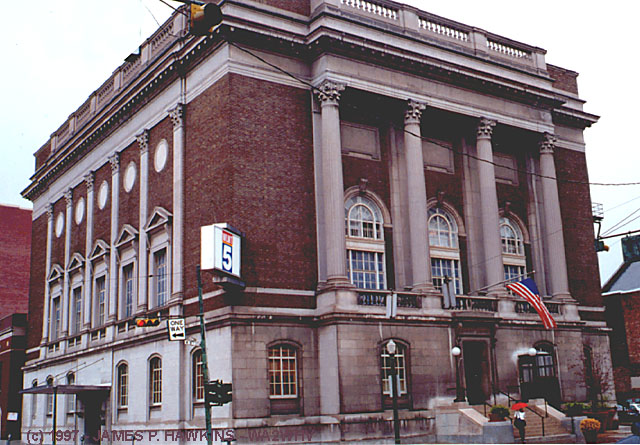
This was originally the Temple, Cincinnati Lodge No. 5, B.P.O. Elks, designed by the Architect, Harry Hake Sr. (my father-in-law's boss). It later housed WLW studios and was named "Crosley Square," which is inscribed over the front door. I took this photograph on August 13, 1997. |
FROM THE BEGINNING
    Broadcast Pro-File
    28243 Royal Road
    Castaic, CA 91384-3028
For more details on this or other radio station histories, you can write to them for a free catalog of historical radio station documents for very reasonable prices. |
PHOTO GALLERY FROM AN EARLY BROCHURE!Please click on this button if you wish to view 17 rarely seen, historic photos scanned from an early brochure from WLW, provided here with permission from WLW. You can view the gallery, which takes longer to load; or the slide show, which sequences through each individual picture. |
|
|
|
|
|
Gallery |
Slide Show |
Antique Radio Classified Covers WLW |
||
|
|
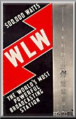
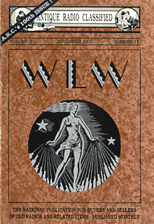
This Antique Radio Classified cover illustration is
from 1930s brochure for the Crosley Corporation radio station WLW. The cover design is reminiscent of the beautiful
Art Deco style of its time. This is probably my favorite issue of ARC with two, interesting related articles entitled: WLW - "The Nation's Station" by Dorothy A. Schecter (pg 4), and "Radio Broadcasting in 1925" by Philip Whitney (pg 8). © Copyright 1997 by John V. Terrey. Reprinted with permission of Antique Radio Classified where it appeared as the cover of the November 1992 issue. For a free sample issue write to: A.R.C., Box 2, Carlisle, MA 01741. |
|
 |
|
WLW Billboard, which was located at Colerain Ave. and W. Galbraith Rd., Cincinnati, OH when this photo was taken in 1997. The light reminded motorists that they could tune in to WLW to hear the news. Note, the antenna on top of the billboard above the light. |
|---|
|
|
Click the icon to hear the news jingle and intro aircheck recorded the morning ot 8/18/97 at 7:00AM after the storms that moved through Cincinnati the previous day. (Recorded with small mike next to tiny SW-100 speaker!) |
|
|
|---|
|
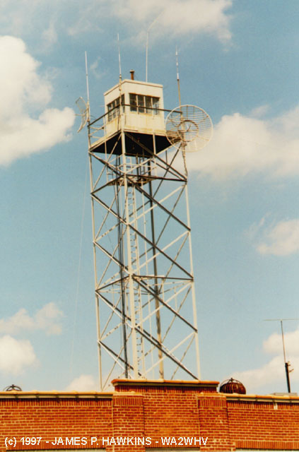
The dish at the upper right of the lookout tower is the 950 MHZ primary input link. |
| The lookout tower was for the armed guards that watched the facility during WWII. There was a spotlight on top
an intercom, heat and power. They could watch over the compound, and remember it extended to the 2 towers across
the road and the demonstration farm they had in operation. The 4 lane road out front was then a gravel lane. There
was serious concern about security at this site. They even had motion sensors and climb detectors on the fences
around the perimeter. This site predated the USIA, later to become the springboard for the Voice of America just
down the road with short-wave operation. There were several Rhombic antennas and Short-wave transmitters here on
site.With calls of WLWO the O standing for overseas. Or the rumor has it. W8XAL was a propagation test transmitter
on 6030 kHz and maybe other frequencies. W8XO was the 500 KW am test callsign. The WLW transmitter was used for
coded communications during the war. I had an old friend since passed that used to tell me about listening at night
with his sweetheart and they would break into programming with some nonsensical string of words. He said it would
begin with the word pelican spoken 3 times then they read some text and a closing. No one of authority has ever
acknowledged or explained. But since WLW could be heard in Europe and the Pacific its use was not hard to figure
out. Hitler himself referred to Crosley as the liar of Cincinnati. Thus the security. He was aware of this operation.
Also WLW experimented with very narrow shift FSK rtty on the Clear Channel channels. But I think that was after
the war. There were receiving loops for WSM, WGN and others. I have found limited documentation here and some old TTY paper with communications with WSM in Nashville. Paul Jellison. |
|
|
|
|
|---|---|---|
|
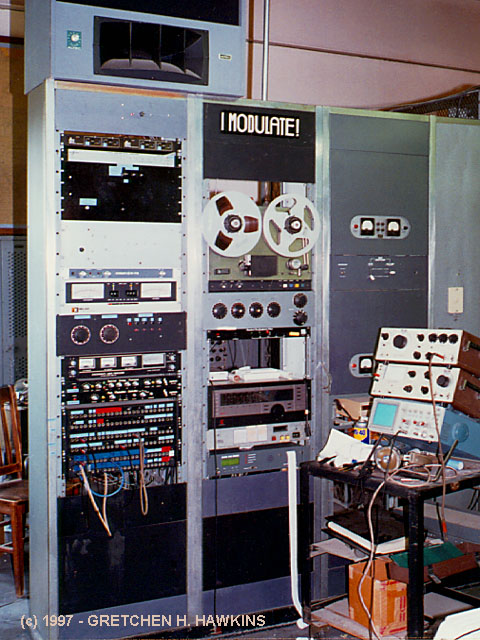
Receiving and audio processing equipment racks receive incoming signal from either the 950 MHZ link or a backup T1 line, process, amplify and pass the signal onto the transmitter modulator input. |
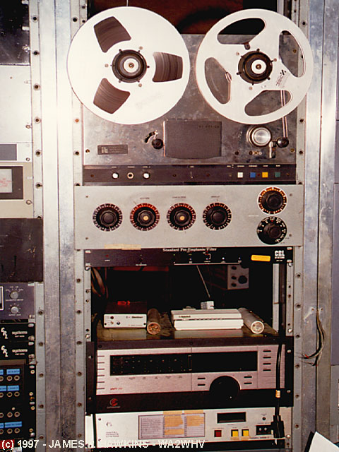
Closup of leftmost rack. |
Closup of middle rack. Second box to bottom is the Unity-AM audio processor which allows engineers to create their own presets for optimal audio processing. Another popular unit of this type is called the Optimod-AM. |
|
|
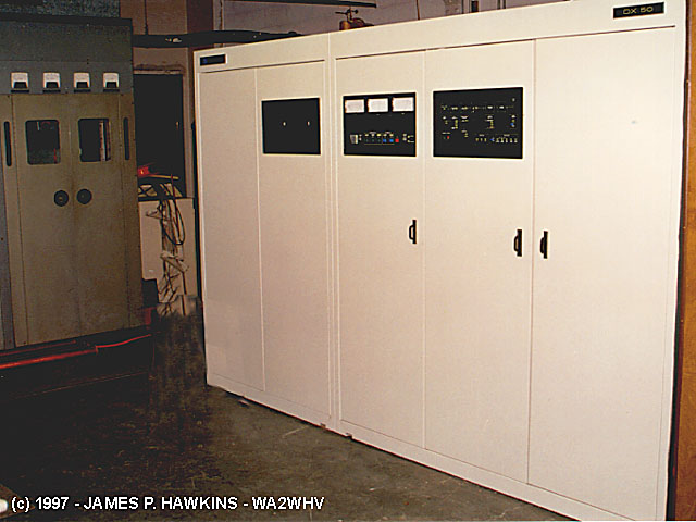
"The 3DX50 BETA [Destinytm] test transmitter has been (and continues to be) in regular, full time, service at WLW since the middle of March 2000. It is being used as the main transmitter with the DX-50 as the backup. It has been very reliable and has experienced lightning hits without damage." According to Geoffrey Mendenhall, V.P. of Harris Advanced Product Development |
|---|---|
|
|
Harris DX-50, 50KW transmitter with digital
modulation. This is the main transmitter. It is completely solid state, small, quiet, cool and relatively maintenance
free. A detailed description of the DX-50 with photos can be found on my WABC Digital AM Transmitter Page Digital Modulation Section. |
|
|
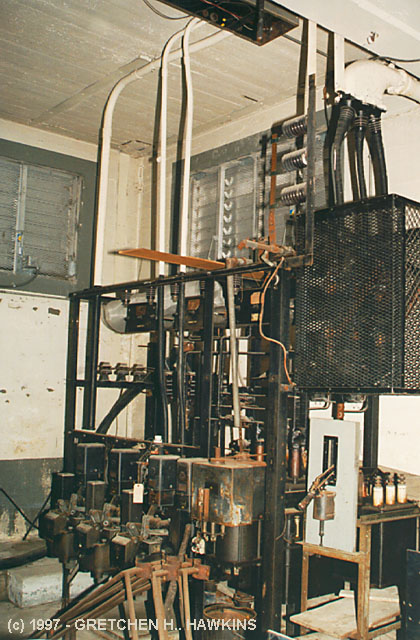
Heavily modified Western Electric A-7 50KW Transmitter. This was the transmitter,
that was used to drive the 500KW monster. It is water cooled and is fully operational. This transmitter uses a
pair of 4CW25000 modulator tubes. This transmitter was operated netween 10:45 and 12:15 |
|
|
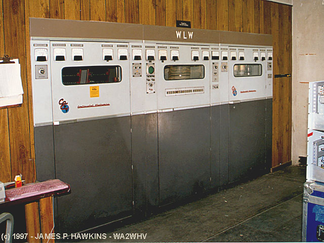
Crosley 50 KW transmitter originally called a "Cathenode" (Cathode/Anode) built on site by R.J. Rockwell. DC coupled back in the 50s. Audio was performance certified by McIntosh as a very Hi-FI transmitter, but very inefficient. It was changed to a high-level, plate modulated transmitter in the late 60s. In the mid 70s, it was converted from a water-cooled to an air-cooled transmitter. |
|
|
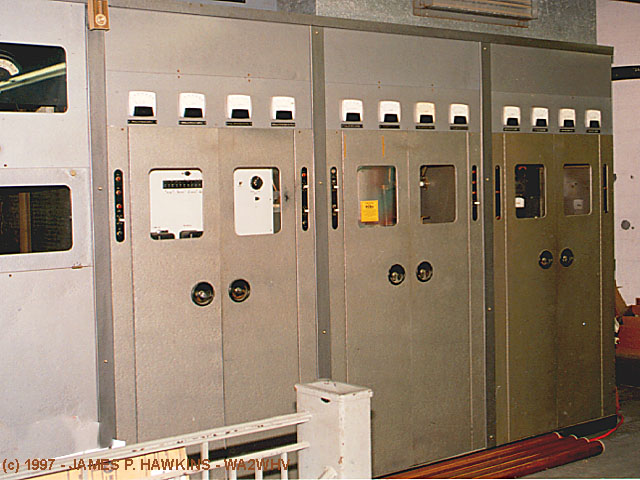
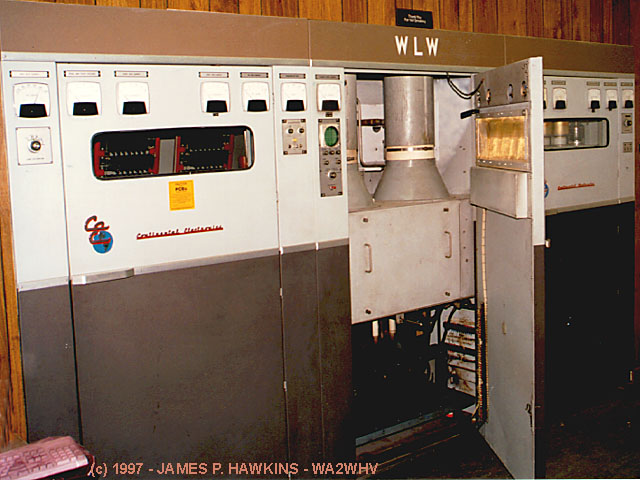
Continental Electronics 317-C1 50KW Screen Modulated, modified Terman Doherty Transmitter, installed in 1975. Basically a Doherty amplifier with modulated screens. A very reliable transmitter. Paul Jellison told me that WGSP Atlanta and KOA Denver is using this transmitter. PA tubes are 4CX35000 (one is visible sitting on the desk). W.H. Doherty was responsible for early successful linear amplifier designs in the 1930s. |
|
|
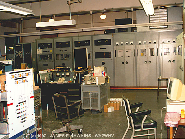
Wide view of transmitter room, a heaven for lovers of old and new transmitter equipment. The Western Electric and Crosley are lined up in the background with a transmitter console in the middle of the room. The DX-50 is visible along the right side and I am standing in front of the Continental TX. There are a number of projects going on in the room which adds a bit of untidyness. |
|
|
|---|
|
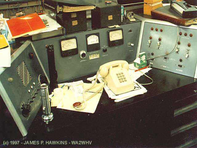
Control console for the Western Electric Transmitter. |
|
|
|
|
|---|---|---|
|
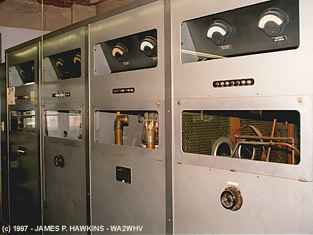
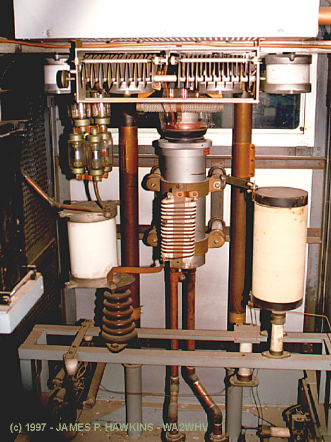
View into back of RF final cabinet. Note the water pipes running to and from the final tube. |
Closup of neutralizing capacitors. |
Closup of final tube. |
|
|
|---|
|
Continental Electronics Transmitter with PA cabinet door open. |
MORE ABOUT THIS SITEThe WLW site is more than just a transmitter site. A great deal of experimenting and building of equipment goes on at the site for both the AM and the television station, WKRC. It seems to have a lab atmosphere with a number of new projects in the works, including a new backup tower, which is to commence construction sometime in October. Paul Jellison, lives with his wife Dee and two sons in the house next door to the transmitter plant. Paul is an Engineering Manager for Jacor, Inc. His official duties for Jacor are to oversee engineering matters for all stations in the Cincinnati area and is the CE of WLW as well. That includes 4 AM signals and 4 FM signals. He has built radio stations from the ground up, from studios to transmitters to towers. |
|
|
|
|---|---|
|
Coax running to the tower is 3 1/8 Heliax and it is pressurized with Nitrogen Gas. |
Looking up at the tower along a guy wire. |
| The tower height was decreased from its original 831 feet to 747 feet. The original height produced a groundwave/skywave cancellation ring which went through Columbus, Indianapolis, Lexington and Louisville. Lowering the mast pushed this ring out farther, away from those population centers. Also, back around 1934, two directional "supressor" towers were constructed across Tylersville Rd. to the south-southwest to reduce skywave radiation toward the Canadian border. CFRB was complaining of interference, so WLW reduced its power to 50KW until the "supressor" towers were in place. As previously stated, this was the first use of skywave directional control for broadcasting. |
| Al Kenyon on how WYGY FM antenna (mounted on the WLW tower) is coupled As posted on rec.radio.broadcasting The WLW tower has a three bay antenna for WYGY 96.5, Chancellor's "Young Country" on the mast at the top of the tower. The feed line goes through an ERI isocoupler before continuing to the tower to avoid shorting out the tower. An isocoupler is essentially a large can (about the size of a 55 gallon drum) with two antennas inside, one of which is mounted on a fiberglass window. The transmission line continues from the antenna on the fiberglass window to the tower, thus the ISO in isocoupler. Many years ago an insulated quarter-wave section was used to get on the tower. (A short across one end of a quarter-wavelength line appears to be an open at the other end.) There was concern that the line section affected the tower's AM radiation. |
|
Accessed
times since August 24, 1997.
E-mail questions to Jim Hawkins